Van Điều Khiển Hành Trình Tuyến Tính Hiệu Suất Cao Có Tay Quay
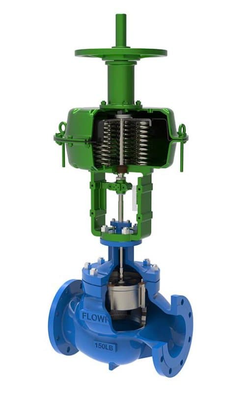
Giới thiệu Van Điều Khiển Hành Trình Tuyến Tính Hiệu Suất Cao Có Tay Quay
Thông số kỹ thuật nhanh Kích thước: 1/2" - 12" (DN15 - DN300) Áp suất: Class 150 - 600 Tiêu chuẩn: IEC 60534, API 608, ASME B16.34 Vật liệu thân van: A216 WCB, A351 CF8M, A182 F316, A182 F51 Vật liệu ghế/trim: PTFE, PEEK, Stellite 6, 316 SS, 17-4PH SS
Thiết kế: Hành trình tuyến tính, trim kiểu nút, truyền động khí nén/điện tích hợp tay quay, đặc tính lưu lượng phần trăm bằng nhau hoặc tuyến tính Cùng Một Van, Một Bổ Sung Quan Trọng
Mọi thứ về van này——trim nút và lồng, đặc tính lưu lượng, vật liệu thân van, cấp áp suất——đều giống hệt van điều khiển hành trình tuyến tính hiệu suất cao FLOWKS tiêu chuẩn. Điều khác biệt là tay quay được lắp trên cụm truyền động. Tay quay đó cho phép bạn điều khiển bằng tay vị trí van khi bộ truyền động không thể thực hiện công việc——sự cố mất nguồn khí, mất điện, bảo trì bộ truyền động, hoặc các chu trình vận hành thử và khởi động nơi bạn cần đặt van ở vị trí cụ thể bằng tay trước khi hệ thống điều khiển tiếp quản. Trên một đường ống quy trình chạy lưu lượng quan trọng, mất điều khiển van nghĩa là mất điều khiển quy trình. Tay quay không phải là phương án dự phòng cho những ngày lười biếng——nó là lối tiếp cận khẩn cấp đến trục van khi hệ thống tự động không thể chạm tới.
Khi Tay Quay Được Sử Dụng——và Không Chỉ Trong Trường Hợp Khẩn Cấp
Khởi động nhà máy là nơi tay quay phát huy giá trị đầu tiên. Trước khi hệ thống điều khiển hoạt động, trước khi các đường khí thiết bị được nạp áp, trước khi DCS tải cấu hình vòng lặp——van cần được định vị bằng tay để thiết lập điều kiện lưu lượng ban đầu. Một người vận hành đến, xoay tay quay, đặt van ở vị trí khởi động mà kỹ sư quy trình đã chỉ định, và giữ nguyên ở đó cho đến khi hệ thống tự động sẵn sàng tiếp nhận điều khiển. Không có tay quay, bạn sẽ cần nạp áp hệ thống khí trước, kích hoạt van qua bộ truyền động, và xác minh vị trí qua phòng điều khiển——một chuỗi dài hơn làm trì hoãn khởi động và tăng độ phức tạp phối hợp.
Việc vận hành thử và hiệu chỉnh vòng điều khiển là kịch bản thứ hai. Khi nhóm kỹ thuật viên hiệu chuẩn vòng điều khiển, họ cần xác minh phản hồi của van ở các vị trí hành trình cụ thể—10%, 25%, 50%, 75%, mở hoàn toàn. Việc điều khiển van bằng tay quay qua các vị trí đó nhanh hơn và trực quan hơn so với việc điều khiển từng bước thông qua hệ thống DCS, đặc biệt là khi vòng điều khiển chưa được cấu hình và bộ truyền động đang phản hồi các tín hiệu ngẫu nhiên thay vì thuật toán điều khiển đã được hiệu chỉnh. Tay quay cho phép nhóm vận hành thử cảm nhận trực tiếp phản hồi cơ học của van—bạn có thể cảm nhận độ cứng, phát hiện sự tiếp xúc giữa van và đế van, xác minh rằng trục van di chuyển tự do trong toàn bộ phạm vi hành trình mà không bị kẹt hoặc gián đoạn. Việc xác minh trực tiếp này là điều mà điều khiển bộ truyền động từ xa không thể cung cấp.
Bảo trì bộ truyền động là tình huống thứ ba. Khi bộ truyền động khí nén cần thay màng, hoặc bộ truyền động điện cần bảo dưỡng động cơ, van phải giữ ở vị trí an toàn trong khi bộ truyền động ngừng hoạt động. Tay quay khóa van ở vị trí mà quy trình yêu cầu——đóng để an toàn cách ly, hoặc mở một phần để duy trì lưu lượng tối thiểu trong khi bộ truyền động được bảo dưỡng. Không có khóa giữ bằng tay đó, bạn sẽ cần hoặc bypass van bằng một phương án thay thế thủ công trong đường ống, hoặc ngừng toàn bộ phân đoạn quy trình. Tay quay giữ cho van hoạt động trong thời gian bộ truyền động ngừng hoạt động.
Cách Tay Quay Tương Tác với Bộ Truyền Động
Tay quay không ghi đè bộ truyền động——nó bổ trợ cho bộ truyền động. Trên bộ truyền động khí nén hồi lò xo, tay quay kết nối với trục qua ly hợp hoặc cơ chế ghi đè bằng tay, cơ chế này ăn khớp khi tay quay được xoay và nhả ra khi bộ truyền động tiếp tục hoạt động. Bạn xoay tay quay——trục di chuyển. Bộ truyền động nhận khí——ly hợp tay quay nhả ra, và bộ truyền động tiếp quản. Không có xung đột giữa vận hành bằng tay và tự động; cơ chế chuyển đổi giữa chúng mà không yêu cầu người vận hành phải chuyển chế độ thủ công. Trên bộ truyền động điện, tay quay thường ăn khớp qua cơ chế nhả ly hợp——kéo cần, xoay tay quay, đẩy cần trở lại để quay lại vận hành bằng động cơ. Trình tự chuyển đổi đủ đơn giản để người vận hành có thể thực hiện trong vài giây khi khẩn cấp.
Cụm tay quay FLOWKS được định cỡ phù hợp với khả năng lực đẩy của bộ truyền động. Đường kính tay quay, ren kết nối trục, và định mức mô-men xoắn ghi đè được tính toán để cho phép một người vận hành duy nhất di chuyển van qua toàn bộ phạm vi hành trình chống lại chênh áp tối đa——không chỉ ở điều kiện không áp suất. Nếu bạn cần đóng van chống lại áp suất đường ống đầy đủ bằng tay, tay quay phải cung cấp đủ lợi thế cơ học để thực hiện điều đó. Việc định cỡ đó không phải là tùy chọn; nó là một phần của gói kỹ thuật.
Mọi Thứ Khác——Giống Hệt Cấu Hình Tiêu Chuẩn
Tùy chọn phích cắm và lồng van: 316 SS, 17-4PH, phủ cứng Stellite 6——cùng lựa chọn, cùng logic ứng dụng. Đặc tính lưu lượng: phần trăm đều...
Thông Số Kỹ Thuật
| Size Range | 1/2" - 24" |
| Pressure Class | Class150~2500 |
| Design Standard | ISA 75, IEC 60534 |
| Parent Standards | ISA 75, IEC 60534 |
| Parent Size Range | 1" - 24" |
| Parent Pressure Class | Class 150 - 1500 |
Tải xuống sản phẩm
| Phạm Vi Cỡ | 1/2" - 24" |
| Lớp Áp Suất | Class150~2500 |
| Tiêu Chuẩn Thiết Kế | ISA 75, IEC 60534 |
Cần Báo Giá?
Contact our engineering team for pricing and technical support on Van Điều Khiển Hành Trình Tuyến Tính Hiệu Suất Cao Có Tay Quay.
Request a QuoteTìm Kiếm Thêm Giải Pháp?
Khám phá dải sản phẩm được thiết kế cho thách thức ngành của bạn.
Ball Valves
FLOWKS offers floating ball valve, trunnion mounted ball valve and top entry ball valve for oil & gas, petrochemical and power generation. Designed per API 6D, API 608 and ASME B16.34.
DBB Valves
FLOWKS Double Block & Bleed (DBB) valves provide dual isolation with bleed verification in a single compact body. Replacing traditional multi-valve installations, FLOWKS DBB valves reduce weight, space and potential leak paths. Available in bolted bonnet, all-welded and expanding gate designs per API 6D and API 607.
Gate Valves
FLOWKS gate valves for isolation service in piping systems. Flexible wedge, solid wedge, slab and expanding gate designs per API 600, API 602 and ASME B16.34.
Globe Valves
FLOWKS globe valves for throttling and isolation. Standard, angle, Y-pattern and bellows seal configurations per API 602 and BS 1868.