Van Điều Khiển Giảm Áp Đa Cấp Kiểu Mê Cung
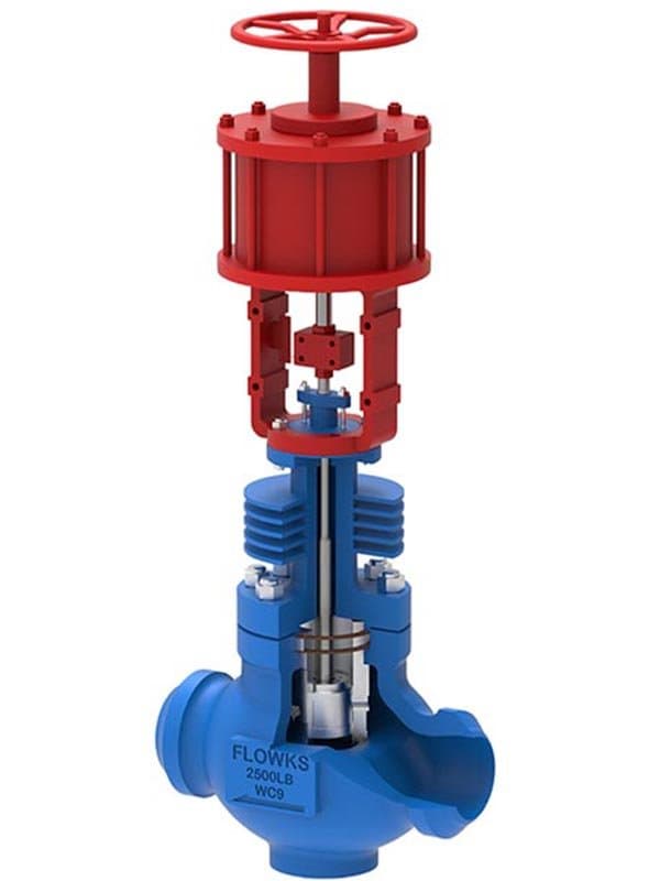
Giới thiệu Van Điều Khiển Giảm Áp Đa Cấp Kiểu Mê Cung
Thông số kỹ thuật nhanh Kích thước: 1" - 12" (DN25 - DN300) Áp suất: Loại 150 - 2500 Tiêu chuẩn: IEC 60534, ASME B16.34, API 6D (cấu hình đường ống) Vật liệu thân van: A216 WCB, A351 CF8M, A182 F51, A182 F53
Vật liệu bộ tiết lưu: Stellite 6, 316 SS, 17-4PH SS, lớp phủ Inconel 625
Thiết kế: Bộ tiết lưu đa tầng kiểu mê cung, lên đến 20+ tầng giảm áp, chống xâm thực, chống bay hơi chớp, độ ồn thấp
Chênh áp cao. Tốc độ cao. Hư hại lớn——Trừ Khi Bạn Chia Nhỏ Chênh Áp Thành Nhiều Bước.
Khi van điều khiển giảm áp từ 1000 psi xuống 50 psi trong một bước duy nhất, tốc độ môi chất qua vena contracta (điểm hẹp nhất trong đường dẫn dòng) đạt mức cực cao——hàng trăm feet mỗi giây trong một số cấu hình. Tốc độ đó tạo ra ba cơ chế phá hủy đồng thời: bọt xâm thực hình thành khi áp suất cục bộ giảm xuống dưới áp suất hơi, sau đó vỡ với lực nổ lên bề mặt bộ tiết lưu; bay hơi chớp xảy ra khi áp suất hạ lưu duy trì dưới áp suất hơi và môi chất hóa hơi một phần qua van, tạo ra dòng hai pha tốc độ cao ăn mòn kim loại như phun cát; và bản thân tốc độ hỗn loạn gây rung động, tiếng ồn vượt quá 100 dB, và mỏi cơ học trong bộ tiết lưu và thân van. Bộ tiết lưu một tầng xử lý chênh áp vừa phải——có thể 100-200 psi chênh lệch trước khi hư hại xâm thực bắt đầu tích tụ. Trên mức đó, van phải được sửa chữa lại mỗi vài tháng, hoặc hỏng hóc thảm khốc khi ăn mòn tạo lỗ xuyên qua thành lồng.
Bộ tiết lưu đa tầng kiểu mê cung chia tổng chênh áp thành một chuỗi các bước nhỏ tăng dần——mỗi bước giảm áp một phần được kiểm soát, và chuỗi tích lũy đưa môi chất từ áp suất đầu vào đến áp suất đầu ra mà không có bước nào vượt quá ngưỡng xâm thực. Thay vì 1000 psi giảm xuống 50 psi trong một chuyển đổi dữ dội, đường mê cung có thể mất 20 tầng: 1000→950→900→850→...→50. Chênh áp mỗi tầng duy trì dưới ngưỡng khởi phát xâm thực, tốc độ cục bộ nằm trong giới hạn kiểm soát, và môi chất đạt áp suất đầu ra sau khi đi qua đường giảm áp có kiểm soát, dần dần thay vì một lần giãn nở dữ dội. Không có bọt xâm thực. Không có ăn mòn do bay hơi chớp. Không có rung động phá hủy. Mức tiếng ồn giảm 20-40 dB so với bộ tiết lưu một tầng ở cùng tổng chênh áp. Tuổi thọ bộ tiết lưu kéo dài từ vài tháng đến vài năm——đôi khi hàng chục năm——vì các điều kiện dòng chảy phá hủy bộ tiết lưu một tầng đơn giản không tồn tại trong đường dòng mê cung.
Cách thức hoạt động của Đường Mê Cung — Những khúc cua, sự mở rộng và sự giảm tốc có kiểm soát
Bộ tiết lưu mê cung là cụm đĩa xếp chồng——nhiều đĩa gia công chính xác với các kênh dẫn phức tạp xếp chồng lên nhau tạo thành đường giảm áp hoàn chỉnh. Mỗi đĩa chứa một tập hợp các đoạn dẫn đưa môi chất qua một chuỗi các khúc quanh, giãn nở, và thay đổi hướng có kiểm soát. Các khúc quanh buộc môi chất đổi hướng——giảm tốc độ và chuyển động năng trở lại thành áp suất thông qua tiêu tán nhiễu loạn. Sự giãn nở tăng tiết diện đoạn dẫn——cho phép môi chất lan rộng và chậm lại trước khi tập hợp khúc quanh tiếp theo nén nó lại. Hiệu quả tích lũy: mỗi đĩa giảm áp một mức cụ thể, và cụm đĩa giảm tổng áp suất từ đầu vào đến đầu ra qua chuỗi kết hợp các mức tăng. Số lượng đĩa (và do đó số tầng) được xác định bởi tổng chênh áp mà van cần xử lý——chênh áp tổng cao hơn cần nhiều tầng hơn để giữ mỗi bước riêng lẻ trong giới hạn an toàn. Cấu hình bộ tiết lưu mê cung FLOWKS dao động từ vài tầng cho chênh áp vừa phải đến 20+ tầng cho giảm áp cực cao từ Class 2500 xuống dịch vụ phân phối áp suất thấp.
Hình dạng đĩa không ngẫu nhiên——nó được thiết kế cho hồ sơ chênh áp cụ thể mà ứng dụng yêu cầu. Hình dạng kênh dẫn, góc quay, tỷ lệ giãn nở, và tiết diện đoạn dẫn trên mỗi đĩa được tính toán để cung cấp mức giảm áp mục tiêu mỗi tầng trong khi duy trì tốc độ trong phạm vi thiết kế. Các tổng chênh áp khác nhau yêu cầu hình dạng đĩa khác nhau——tổng chênh áp 500 psi sử dụng cụm đĩa khác với tổng chênh áp 2000 psi, vì mức giảm mỗi tầng và quản lý tốc độ ở mỗi tầng khác nhau. Đó là lý do bộ tiết lưu mê cung phụ thuộc ứng dụng: cụm đĩa được thiết kế cho hồ sơ áp suất đầu vào-đầu ra thực tế, không phải lắp ráp từ số tầng tiêu chuẩn với hy vọng các tầng tình cờ khớp với điều kiện quy trình.
Van mê cung được chỉ định ở đâu——Các ứng dụng có độ sụt áp cao. Điều tiết nước cấp lò hơi——nước đầu vào ở áp suất xả bơm cao cần được giảm xuống áp suất vận hành của lò hơi, với độ sụt áp thường vượt quá 500-1000 psi. Giảm áp hơi——đường ống hơi áp suất cao cấp cho hệ thống phân phối áp suất thấp, nơi mà bộ tiết lưu một tầng sẽ tạo ra cavitation và mức tiếng ồn vi phạm tiêu chuẩn sức khỏe nghề nghiệp của nhà máy. Điều tiết xả máy nén——khí áp suất cao từ trạm máy nén cấp cho mạng lưới đường ống áp suất thấp hơn, nơi mà hiện tượng bay hơi chớp nhoáng và xói mòn sẽ phá hủy bộ tiết lưu tiêu chuẩn chỉ trong vài tuần. Giảm áp quy trình hóa dầu——xả lò phản ứng ở áp suất cao cấp cho thiết bị phân tách hạ nguồn ở áp suất vận hành thấp hơn, nơi mà hóa chất môi trường kết hợp với vận tốc cao làm cho tốc...
Thông Số Kỹ Thuật
| Size Range | 2”-24” |
| Pressure Class | Class300-2500 |
| Design Standard | ISA 75, IEC 60534 |
| Body Materials | WCB, WC6, WC9, CF8M, duplex steel, Monel and titanium |
| Parent Standards | ISA 75, IEC 60534 |
| Parent Size Range | 1" - 24" |
| Parent Pressure Class | Class 150 - 1500 |
Tải xuống sản phẩm
| Phạm Vi Cỡ | 2”-24” |
| Lớp Áp Suất | Class300-2500 |
| Tiêu Chuẩn Thiết Kế | ISA 75, IEC 60534 |
| Vật Liệu Thân Van | WCB, WC6, WC9, CF8M, duplex steel, Monel and titanium |
Cần Báo Giá?
Contact our engineering team for pricing and technical support on Van Điều Khiển Giảm Áp Đa Cấp Kiểu Mê Cung.
Request a QuoteTìm Kiếm Thêm Giải Pháp?
Khám phá dải sản phẩm được thiết kế cho thách thức ngành của bạn.
Ball Valves
FLOWKS offers floating ball valve, trunnion mounted ball valve and top entry ball valve for oil & gas, petrochemical and power generation. Designed per API 6D, API 608 and ASME B16.34.
DBB Valves
FLOWKS Double Block & Bleed (DBB) valves provide dual isolation with bleed verification in a single compact body. Replacing traditional multi-valve installations, FLOWKS DBB valves reduce weight, space and potential leak paths. Available in bolted bonnet, all-welded and expanding gate designs per API 6D and API 607.
Gate Valves
FLOWKS gate valves for isolation service in piping systems. Flexible wedge, solid wedge, slab and expanding gate designs per API 600, API 602 and ASME B16.34.
Globe Valves
FLOWKS globe valves for throttling and isolation. Standard, angle, Y-pattern and bellows seal configurations per API 602 and BS 1868.