Gauge Block-NonoFlange DBB
About
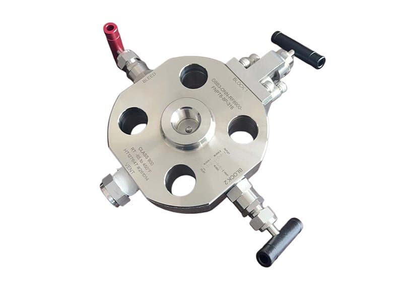
1/2" - 2" (DN15 - DN50) Class 150 - 1500 / up to 10,000 psi (needle-type configurations) API 6D, API 607, ASME B16.34, ISO 15848 A182 F316, A182 F51, A182 F53 PTFE, PEEK, metal-to-metal (Stellite 6) Gauge block body with nonoflange (no-flange) connection, double block & bleed with single bleed port, compact instrumentation valve
What a Gauge Block DBB Does——and Why Instrument Engineers Specify It
Pressure gauges, transmitters, and instrument taps need isolation for calibration, replacement, and verification without shutting down the main process line. That isolation has to be double——one blocking seat isn't enough when the process line carries 1500 psi of hydrocarbon or 10,000 psi of hydraulic fluid. A single seat could leak. A single seat could fail. And if it does, the process media reaches the instrument and the bleed port simultaneously——the technician gets hit with live process pressure while trying to verify zero. That's why the API 6D definition of Double Block and Bleed requires two independent sealing boundaries with a bleed cavity between them: the first seat blocks upstream pressure, the second seat blocks downstream pressure toward the instrument, and the bleed cavity between the two seats gives you a verified zero-pressure zone where you can confirm that both seats are holding before you open the instrument side. A gauge block DBB valve puts both blocking seats and the bleed cavity into a single compact body that mounts directly at the instrument connection point——no separate valves, no tee-fitting assemblies, no multiple potential leak paths between the blocking and bleeding functions.
Nonoflange——No Flange, No Bolting, Direct Thread-On Installation
The nonoflange connection means the valve body threads directly onto the instrument connection point——typically a 1/2" or 3/4" NPT threaded tap on the pipe or vessel wall——without any flange bolting between the valve and the process. That direct thread-on mounting eliminates the flange gasket as a potential leak path (flanges leak at the gasket; threaded connections don't have gaskets), reduces the installation envelope (no flange bolting circle, no gasket alignment, no bolt tensioning procedure——just thread the valve onto the tap and wrench-tighten), and keeps the overall assembly height down to the minimum practical dimension for instrument installation. Flanged gauge block DBBs exist (FLOWKS manufactures those too——see the Flange DBB series), and they serve applications where the instrument connection point is flanged rather than threaded. But for the majority of instrumentation taps on process piping——which are NPT-threaded pipe bosses welded onto the main line——the nonoflange version is the simpler, more compact, and more direct installation option. No flange to bolt. No gasket to align. No flange bolting procedure to execute. Thread it on. Wrench it tight. Done.
The compact body geometry is a functional requirement, not a cosmetic preference. Instrument installations have limited physical space——the gauge or transmitter sits on the end of the valve, and both have to fit within the pipe rack or vessel skirt clearance envelope. A gauge block body with nonoflange threading keeps the total assembly length (process connection to instrument flange or thread) at the minimum dimension that still houses both blocking seats and the bleed cavity. Shorter assembly length means less protrusion from the pipe wall, less vulnerability to impact damage from maintenance activity in congested pipe rack areas, and less weight on the threaded pipe boss (threaded connections carry bending loads from the assembly weight——shorter and lighter means lower bending stress on the thread engagement).
Two Seats and a Bleed——The Functional Architecture of DBB Isolation
The gauge block body contains two independent seating elements arranged in series along the flow path——the upstream (process-side) seat and the downstream (instrument-side) seat. Each seat seals independently: the upstream seat blocks process pressure from entering the bleed cavity between the two seats, and the downstream seat blocks any pressure that might leak past the upstream seat from reaching the instrument connection. The bleed port sits between the two seats——a small-diameter port (typically 1/4" NPT) that vents the cavity to atmosphere or to a closed drain system. In operation: both seats closed, bleed valve open——the bleed port verifies zero pressure in the cavity between the seats, confirming that both blocking boundaries are holding. If the upstream seat leaks, process pressure enters the cavity and vents through the bleed port——the technician sees live pressure at the bleed and knows the upstream seat isn't holding. If the downstream seat leaks, pressure from the cavity (if any) reaches the instrument side——the technician sees pressure at the instrument connection and knows...
Technical Specifications
| Size Range | 1/2"-2" |
| Pressure Class | Class 150 - 2500 |
| Design Standard | EEMUA PUB NO182 |
| Body Materials | A105、SS304、SS316、F51, F55, F53, Hastelloy C、Monel 400 |
| Parent Standards | API 6D, API 607, API 608, ASME B16.34, ISO 15848 |
| Parent Size Range | 2" - 24" |
| Parent Pressure Class | Class 150 - 1500 |
Product Downloads
| Size Range | 1/2"-2" |
| Pressure Class | Class 150 - 2500 |
| Design Standard | EEMUA PUB NO182 |
| Body Materials | A105、SS304、SS316、F51, F55, F53, Hastelloy C、Monel 400 |
Need a quote?
Contact our engineering team for pricing and technical support on Gauge Block-NonoFlange DBB.
Request a QuoteLooking for more options?
Explore our complete range of industrial valves or contact us for custom solutions.
Ball Valves
FLOWKS offers floating ball valve, trunnion mounted ball valve and top entry ball valve for oil & gas, petrochemical and power generation. Designed per API 6D, API 608 and ASME B16.34.
Gate Valves
FLOWKS gate valves for isolation service in piping systems. Flexible wedge, solid wedge, slab and expanding gate designs per API 600, API 602 and ASME B16.34.
Globe Valves
FLOWKS globe valves for throttling and isolation. Standard, angle, Y-pattern and bellows seal configurations per API 602 and BS 1868.
Check Valves
FLOWKS check valves prevent reverse flow. Dual plate, swing, tilting disc and lift check designs per API 594 and BS 1868.