Product Range
Complete range of industrial valves for every application.
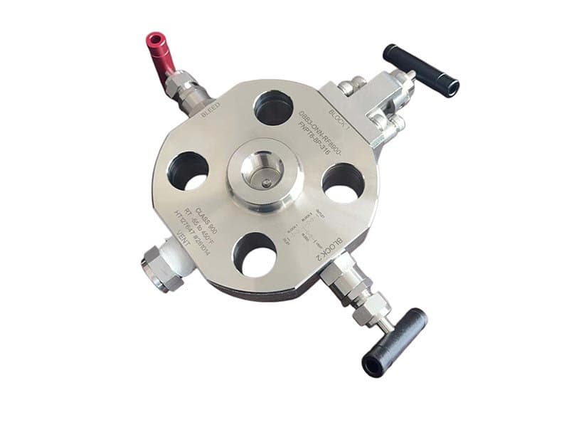
Gauge Block-NonoFlange DBB
Quick Specs 1/2" - 2" (DN15 - DN50) Class 150 - 1500 / up to 10,000 psi (needle-type configurations) API 6D, API 607, ASME B16.34, ISO 15848 A182 F316, A182 F51, A182 F53 PTFE, PEEK, metal-to-metal (Stellite 6) Gauge block body with nonoflange (no-flange) connection, double block & bleed with single bleed port, compact instrumentation valve What a Gauge Block DBB Does——and Why Instrument Engineers Specify It Pressure gauges, transmitters, and instrument taps need isolation for calibration, replacement, and verification without shutting down the main process line. That isolation has to be double——one blocking seat isn't enough when the process line carries 1500 psi of hydrocarbon or 10,000 psi of hydraulic fluid. A single seat could leak. A single seat could fail. And if it does, the process media reaches the instrument and the bleed port simultaneously——the technician gets hit with live process pressure while trying to verify zero. That's why the API 6D definition of Double Block and Bleed requires two independent sealing boundaries with a bleed cavity between them: the first seat blocks upstream pressure, the second seat blocks downstream pressure toward the instrument, and the bleed cavity between the two seats gives you a verified zero-pressure zone where you can confirm that both seats are holding before you open the instrument side. A gauge block DBB valve puts both blocking seats and the bleed cavity into a single compact body that mounts directly at the instrument connection point——no separate valves, no tee-fitting assemblies, no multiple potential leak paths between the blocking and bleeding functions. Nonoflange——No Flange, No Bolting, Direct Thread-On Installation The nonoflange connection means the valve body threads directly onto the instrument connection point——typically a 1/2" or 3/4" NPT threaded tap on the pipe or vessel wall——without any flange bolting between the valve and the process. That direct thread-on mounting eliminates the flange gasket as a potential leak path (flanges leak at the gasket; threaded connections don't have gaskets), reduces the installation envelope (no flange bolting circle, no gasket alignment, no bolt tensioning procedure——just thread the valve onto the tap and wrench-tighten), and keeps the overall assembly height down to the minimum practical dimension for instrument installation. Flanged gauge block DBBs exist (FLOWKS manufactures those too——see the Flange DBB series), and they serve applications where the instrument connection point is flanged rather than threaded. But for the majority of instrumentation taps on process piping——which are NPT-threaded pipe bosses welded onto the main line——the nonoflange version is the simpler, more compact, and more direct installation option. No flange to bolt. No gasket to align. No flange bolting procedure to execute. Thread it on. Wrench it tight. Done. The compact body geometry is a functional requirement, not a cosmetic preference. Instrument installations have limited physical space——the gauge or transmitter sits on the end of the valve, and both have to fit within the pipe rack or vessel skirt clearance envelope. A gauge block body with nonoflange threading keeps the total assembly length (process connection to instrument flange or thread) at the minimum dimension that still houses both blocking seats and the bleed cavity. Shorter assembly length means less protrusion from the pipe wall, less vulnerability to impact damage from maintenance activity in congested pipe rack areas, and less weight on the threaded pipe boss (threaded connections carry bending loads from the assembly weight——shorter and lighter means lower bending stress on the thread engagement). Two Seats and a Bleed——The Functional Architecture of DBB Isolation The gauge block body contains two independent seating elements arranged in series along the flow path——the upstream (process-side) seat and the downstream (instrument-side) seat. Each seat seals independently: the upstream seat blocks process pressure from entering the bleed cavity between the two seats, and the downstream seat blocks any pressure that might leak past the upstream seat from reaching the instrument connection. The bleed port sits between the two seats——a small-diameter port (typically 1/4" NPT) that vents the cavity to atmosphere or to a closed drain system. In operation: both seats closed, bleed valve open——the bleed port verifies zero pressure in the cavity between the seats, confirming that both blocking boundaries are holding. If the upstream seat leaks, process pressure enters the cavity and vents through the bleed port——the technician sees live pressure at the bleed and knows the upstream seat isn't holding. If the downstream seat leaks, pressure from the cavity (if any) reaches the instrument side——the technician sees pressure at the instrument connection and knows...
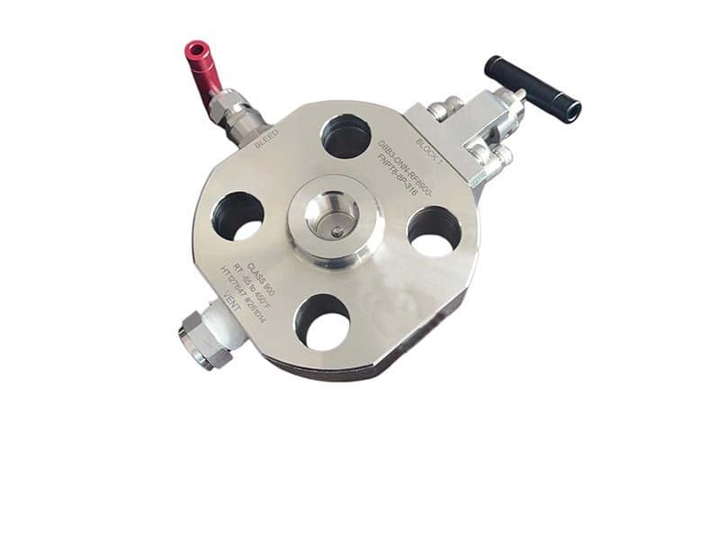
Gauge Block NonoFlange SBB
Quick Specs 1/2" - 2" (DN15 - DN50) Class 150 - 1500 / up to 10,000 psi (needle-type configurations) API 6D, API 607, ASME B16.34, ISO 15848 A182 F316, A182 F51, A182 F53 PTFE, PEEK, metal-to-metal (Stellite 6) Gauge block body with nonoflange connection, single block & bleed with bleed verification port, compact instrumentation valve SBB vs DBB——One Seat or Two, and When One Is Enough Double Block and Bleed (DBB) provides two independent sealing boundaries with a verified zero-pressure cavity between them——the maximum isolation assurance available in a single valve body. But not every instrument isolation application needs maximum assurance. Some applications need verified isolation with a bleed check, but the process conditions don't demand two independent blocking boundaries: low-pressure utility lines, non-hazardous media (water, air, nitrogen), instrument taps on non-flammable service where the consequence of a single seat leak is a gauge reading error, not a safety incident. For those applications, Single Block and Bleed (SBB) provides one blocking seat and one bleed verification port——enough isolation to remove the instrument safely (the seat blocks process pressure, the bleed port verifies the seat is holding before the instrument side gets opened), but with only one sealing boundary instead of two. The trade-off is straightforward: one seat instead of two means fewer components, shorter assembly length, lower cost, and simpler operation——but only one blocking boundary, not two independent ones. If that single seat fails, there's no backup seat to maintain isolation. The bleed port reveals the failure (process pressure appears at the bleed), but the isolation is gone until the seat gets repaired. FLOWKS gauge block SBB valves use the same compact body geometry as the DBB version——nonoflange thread-on mounting, direct NPT connection to the instrument tap, minimum assembly height——but with one blocking seat instead of two. The bleed port sits on the downstream side of the single blocking seat, providing the verification function that distinguishes SBB from simple single-block isolation without bleed capability. With the blocking seat closed and the bleed valve open, zero pressure at the bleed port confirms the single seat is holding. If process pressure appears at the bleed, the seat has failed——the isolation is compromised and the instrument side gets exposed to live process pressure. That verification capability (bleed-check before opening the instrument side) is what makes SBB a safer isolation method than a simple single-block valve without bleed——the technician doesn't assume the seat is holding, the technician verifies it through the bleed port. But it's still only one seat——if the verification reveals a failure, there's no backup. When SBB Is the Right Specification——and When It Isn't The decision between SBB and DBB isn't about preference or cost optimization——it's about consequence analysis. What happens if the single blocking seat leaks or fails? If the consequence is a gauge reading error or a transmitter calibration drift on a non-hazardous utility line——SBB is adequate. The bleed port reveals the failure, maintenance replaces the seat, and the process continues. If the consequence is exposure to toxic, flammable, or high-pressure media that would create a safety incident or environmental release——DBB is mandatory. The single seat in SBB provides verified isolation when it's holding, but it provides no backup when it fails. On hazardous service, that's unacceptable——the second seat in DBB provides the backup that maintains isolation even when the first seat fails, and the bleed cavity reveals which seat has failed without losing overall isolation capability. Regulatory frameworks and industry standards increasingly default to DBB for process isolation on hydrocarbon, chemical, and high-pressure pipelines——the API 6D definition of Double Block and Bleed is the baseline specification for new installations on flammable and toxic service. SBB remains appropriate for non-hazardous utility service (instrument air, nitrogen blanketing, low-pressure water, HVAC systems) where the isolation consequence is operational inconvenience, not safety risk. On those applications, SBB's simpler architecture (one seat, one bleed, fewer components, shorter assembly) provides verified isolation with adequate safety margin——the cost and complexity reduction of eliminating the second seat is justified by the lower consequence of a single-seat failure. The Bleed Port——Same Verification Function, Positioned After One Seat Instead of Two In a DBB valve, the bleed port sits between two blocking seats——it vents the cavity between them and verifies that both upstream and downstream seats are holding simultaneously. In an SBB valve, the bleed port sits downstream of the single blocking seat——it vents the space...
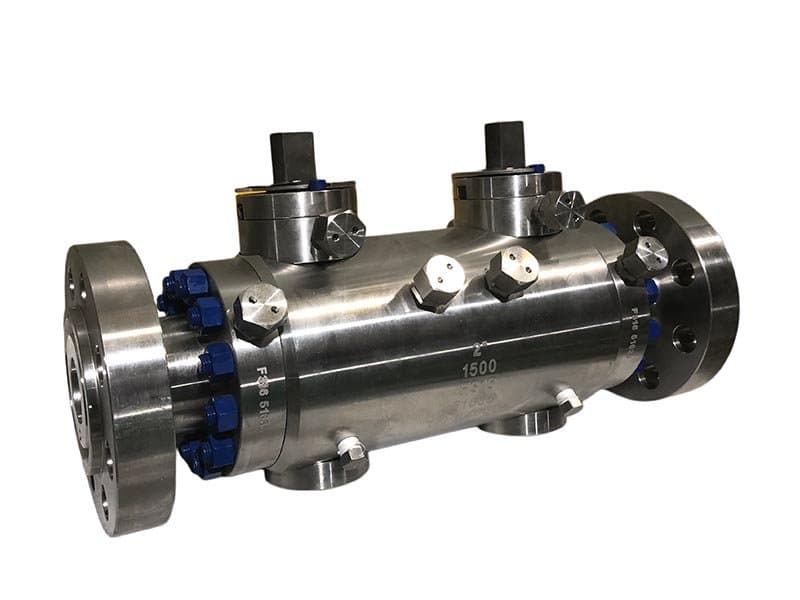
Trunnion Double Block & Bleed DBB
Quick Specs 2" - 24" (DN50 - DN600) Class 150 - 1500 API 6D, API 607, ASME B16.34, ISO 15848 A216 WCB, A351 CF8M, A182 F51, A182 F53 PTFE, Nylon, PEEK, metal-to-metal (Stellite 6) Trunnion-mounted ball with spring-loaded seats, double block & bleed in single body, side-entry or top-entry maintenance access Pipeline Isolation That Doesn't Trust One Seat——Because Pipeline Consequences Don't Allow It A pipeline isolation valve sits between sections of process piping carrying hydrocarbon, chemical, or high-pressure gas——media where the consequence of isolation failure isn't a gauge reading error, it's a safety incident, an environmental release, or a regulatory violation. On those applications, one blocking seat isn't sufficient even when it's holding——because the consequence of that one seat failing is unacceptable. A single-block valve provides isolation from one sealing boundary; if that boundary leaks, the media reaches the downstream section that was supposed to be isolated. A trunnion DBB valve provides isolation from two independent sealing boundaries with a verified zero-pressure cavity between them——the upstream seat blocks pressure from the active pipeline section, the downstream seat blocks pressure toward the isolated section, and the bleed cavity between the two seats gives you a verified zero-pressure zone that confirms both seats are holding before the downstream section gets opened for maintenance, inspection, or hot-tap operations. Two independent seats, two independent failure modes, one verified isolation status visible through the bleed port. The trunnion-mounted ball architecture provides the structural platform for two independent spring-loaded seats within a single valve body. The ball is anchored by upper and lower trunnion pins——it doesn't float under pressure differential like a floating ball valve. The two seat rings sit on opposite sides of the ball, each independently spring-loaded against the ball surface. When the ball rotates to the closed position, both seats seal simultaneously——the upstream seat against upstream pressure, the downstream seat against downstream pressure, both independent, both verifiable through the bleed cavity. That trunnion architecture is what makes DBB feasible at larger bore sizes——a floating ball valve has one sealing direction (the ball pushes against the downstream seat under upstream pressure), but a trunnion valve has two independent sealing directions (each spring-loaded seat pushes against the ball from its own side). Two seats. Two springs. Two independent sealing forces. One verified isolation cavity between them. Why Trunnion DBB Replaces the Old Three-Valve Assembly Before single-body DBB valves became the standard pipeline isolation specification, the industry used three separate valves to achieve double block and bleed: two isolation valves (one upstream, one downstream) and one bleed valve in a tee fitting between them. That three-valve assembly works——it provides two blocking boundaries and a bleed verification port——but it has four inherent problems that a single-body trunnion DBB eliminates. First: multiple potential leak paths. Three valves means three valve bodies, three sets of body-to-piping connections, three bonnet-to-body gaskets, and the tee fitting connections between the three valves——each connection is a potential external leak path. A single-body DBB eliminates all the inter-valve connections——both blocking seats and the bleed port are inside one body, with no external connections between the blocking and bleeding functions except the single bleed port to atmosphere or drain. Fewer external connections means fewer potential leak paths. Second: larger installation envelope. Three separate valves with a tee fitting occupy significantly more pipe rack space than a single-body DBB——the three-valve assembly length is the combined length of two isolation valves plus the tee fitting, while the single-body DBB fits within a single valve body length. On congested pipe rack installations where space allocation is a constraint, the single-body DBB's compact footprint is a practical advantage that goes beyond aesthetics. Third: higher total weight. Three valve bodies plus a tee fitting weigh more than one DBB body——more steel in the pipe rack, more weight on pipe supports, more structural loading. Weight reduction isn't just a convenience——on large-bore pipeline installations, the weight difference between a three-valve assembly and a single-body DBB can affect pipe support design and stress analysis calculations. Fourth: sequential operation complexity. Operating three separate valves requires a specific sequence: close the upstream isolation valve, open the bleed valve, verify zero pressure at the bleed, close the downstream isolation valve, then proceed with the downstream work. That sequence has to be executed correctly...
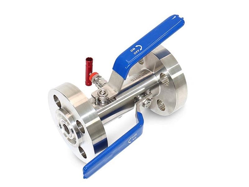
Flange Block-Bleed DBB
Quick Specs 2" - 20" (DN50 - DN500) Class 150 - 600 API 6D, API 607, ASME B16.34, ISO 15848 A216 WCB, A351 CF8M, A182 F51 PTFE, Nylon, PEEK, metal-to-metal (Stellite 6) Flanged end connections (RF/RTJ), bolted bonnet, double block & bleed in single body, manual or actuated operation Flanged Connections——Where the Pipeline Specification Calls for Bolted End Connections The flanged DBB valve serves the same isolation function as the trunnion DBB——two independent blocking seats with a verified bleed cavity between them——but with flanged end connections to the pipeline instead of butt-weld. Flanged connections (raised face or ring-type joint per ASME B16.5) are the standard pipeline connection method for Class 150 through Class 600 in many facility specifications——particularly on process piping systems where maintenance accessibility requires bolted connections that can be disassembled without cutting and re-welding the pipe. A butt-weld DBB valve (like the FLOWKS all-welded DBB series) permanently joins the valve to the pipeline——removal requires cutting the weld and re-welding a replacement. A flanged DBB valve unbolted from the pipeline flanges——four bolts per flange (on smaller sizes) or dozens on larger sizes, but the principle is the same: unbolt, remove, replace, re-bolt. No welding. No hot work permit. No radiographic inspection of replacement welds. That bolted-connection accessibility is the primary reason facilities specify flanged DBB valves on Class 150-600 piping——the maintenance logistics of bolted connections are simpler, faster, and cheaper than welded connections on the pressure classes where flanged joints are structurally adequate. Above Class 600, butt-weld connections become the standard specification because flanged joints at Class 900 and above require heavier bolting, larger gasket surfaces, and higher bolt tensioning loads that push the flanged-connection maintenance complexity beyond practical limits for many installations. The FLOWKS flanged DBB covers Class 150 through Class 600——the pressure range where flanged connections serve the majority of process piping installations and where the bolted-connection maintenance advantage is most valuable. Bolted Bonnet——Maintenance Access Without Removing the Valve from the Pipeline The bonnet (the valve body section that contains the stem, packing, and the upper trunnion bearing) attaches to the body through a bolted bonnet-to-body connection——bolted, not welded. That bolted bonnet design provides maintenance access to the stem packing, the upper trunnion bearing, and the ball-and-seat assembly without removing the entire valve from the pipeline flanges. The maintenance procedure: unbolt the bonnet, lift the bonnet assembly (stem, ball upper pin, packing) out of the body, access the seat rings and ball for inspection or replacement, re-install the bonnet with new gasket, re-bolt, re-torque. The pipeline flanges stay bolted——the valve body stays connected to the pipeline throughout the maintenance operation. That in-line maintenance capability is the same principle that FLOWKS top-entry ball valves use for buried and welded pipeline service——the difference is that the flanged DBB's bolted bonnet serves flanged-connection installations where the pipeline flanges themselves are the primary disassembly point, and the bonnet bolts are the secondary access point for internal trim maintenance. The bonnet-to-body gasket is a critical sealing element——it's the pressure boundary between the body cavity (exposed to pipeline pressure) and the bonnet cavity (exposed to packing and stem). The gasket specification matches the process media and temperature conditions: spiral-wound gaskets (stainless winding with graphite or PTFE filler) for general process service, metal-ring gaskets for high-temperature and fire-safe applications where spiral-wound gaskets would degrade under sustained thermal loading. The gasket gets replaced every time the bonnet gets unbolted——gaskets are one-time sealing elements, not reusable. That replacement requirement is standard maintenance practice across bolted-bonnet valve designs——you don't re-use a gasket on a pressure boundary, you install a new one every time the joint gets re-assembled. Double Block and Bleed——Same Functional Architecture, Flanged Installation Package The DBB isolation architecture inside the flanged body is identical to the trunnion DBB: two independent spring-loaded seats pressing against the trunnion-mounted ball from opposite sides, with a bleed cavity between them that vents through a designated port on the body. The upstream seat blocks process pressure from the active pipeline section. The downstream seat blocks pressure toward the isolated section. The bleed cavity verifies both seats simultaneously——zero pressure at the bleed confirms both blocking boundaries are holding. The functional...
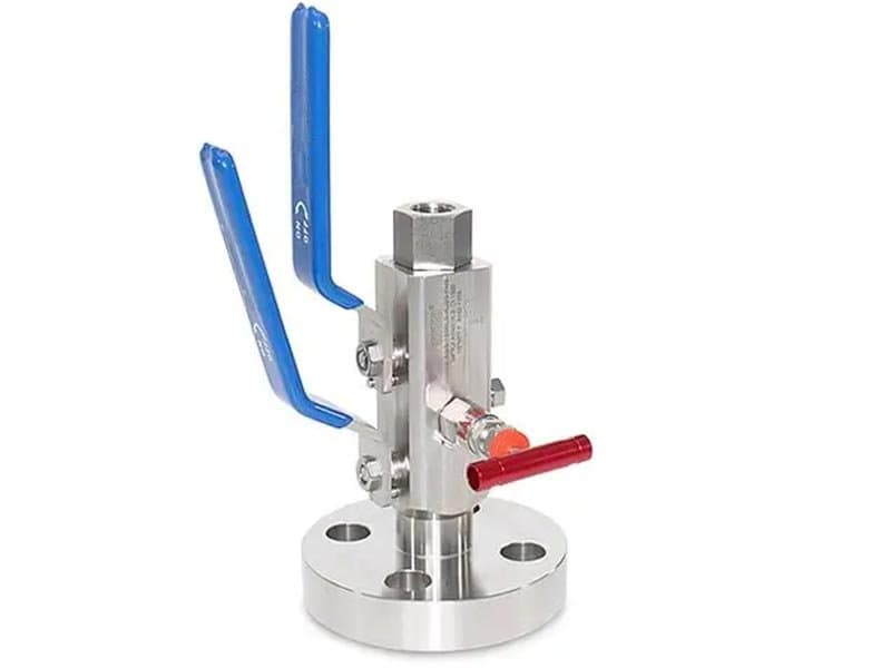
Flange To Screw Needle Type DBB
Quick Specs 1/2" - 1" (DN15 - DN25) up to 10,000 psi (Class 150 - 2500 equivalent) API 6D, API 607, ASME B16.34, ISO 15848 A182 F316, A182 F51, A182 F53 PTFE, PEEK, metal-to-metal (Stellite 6) Flanged process-side connection + threaded (NPT) instrument-side connection, needle-type DBB with compact body, double block & bleed with single bleed port Flange on One End, Screw on the Other——Where the Pipeline Is Flanged but the Instrument Is Threaded Process piping at the instrument connection point often has a flanged isolation valve on the pipeline side and a threaded (NPT) connection at the gauge or transmitter side——the pipeline specification calls for flanged connections above 1" bore for structural integrity and maintenance accessibility, but the instrument connection (gauge, transmitter, pressure switch) is almost always 1/2" NPT threaded because instruments don't have flanged process connections. That mismatch——flanged on one side, threaded on the other——is exactly what this valve addresses. The process-side (upstream) connection is a flanged end (RF or RTJ per ASME B16.5) that bolts directly to the pipeline flange. The instrument-side (downstream) connection is a threaded NPT port that the gauge or transmitter threads onto directly. Two blocking seats and a bleed cavity sit between the flanged upstream connection and the threaded downstream connection——the DBB isolation function spans the entire flow path from flanged pipeline interface to threaded instrument interface, with no additional fittings, adapters, or interconnection leak paths between them. Without this flange-to-screw configuration, the installer has to cobble together a flanged isolation valve, a reducing fitting (flange-to-thread adapter), and a separate bleed valve——three components with two interconnection points (flanged-to-adapter, adapter-to-instrument) that are both potential external leak paths. Each interconnection adds a gasket or thread seal that has to be maintained independently. The flange-to-screw needle-type DBB eliminates both interconnection points——the flanged end bolts directly to the pipeline, the threaded end accepts the instrument directly, and the DBB isolation is inside the single body between them. No adapter. No extra fitting. No interconnection leak paths. One valve body spans the entire connection mismatch. Needle-Type——Compact Body for High-Pressure Instrumentation Taps The needle-type designation means the blocking seats are needle-valve trim rather than ball-valve trim——a tapered needle plug that seats into a matching cone-shaped seat ring, rather than a rotating ball that seals against flat or contoured seat rings. Needle trim has two practical advantages at small bore sizes and high pressures: First: the needle-and-cone seating geometry seals progressively——the needle seats deeper into the cone as closing force increases, creating a line-contact seal that tightens with additional stem torque. That progressive seating behavior gives needle-type valves a mechanical advantage at high pressures where ball-valve seats (which rely on surface-to-surface contact at a defined seat geometry) can struggle to maintain bubble-tight shutoff at pressures above Class 1500. The needle's tapered geometry creates a wedging effect——the more closing torque you apply, the tighter the needle wedges into the cone, and the seal gets progressively tighter rather than reaching a limit defined by the seat's elastic deformation. Second: the needle trim's compact geometry fits inside a body that's smaller than a ball-valve body at the same bore size——the needle assembly (stem, tapered plug, seat cone) occupies less internal volume than a ball assembly (ball, two seat rings, trunnion pins) at 1/2" bore. That compact geometry keeps the overall body dimensions shorter and lighter——critical for instrumentation installations where space allocation at the pipeline tap is limited, and where the weight on the flanged connection has to stay within the flange's structural capacity. The two blocking seats in the needle-type DBB are two independent needle-valve assemblies——one upstream (process-side) needle and one downstream (instrument-side) needle, each with its own stem, seat cone, and operating handle. The bleed port sits between the two needle seats——a third, smaller needle valve that vents the cavity between the two blocking needles. Three stems, three handles, one body. Each needle operates independently——close the upstream needle first, open the bleed needle to verify zero, then close the downstream needle. The sequence is the same as any DBB operation, but the seating mechanism is needle-and-cone rather than ball-and-ring. Two Needles and a Bleed——Independent Sealing, Independent Verification The upstream needle blocks process pressure from the flanged pipeline connection. The downstream needle blocks any pressure that might leak...
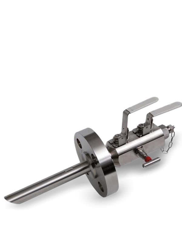
Sampling DBB Needle Valve
Quick Specs 1/4" - 1/2" (DN8 - DN15) up to 10,000 psi / Class 150 - 2500 equivalent API 6D, ISO 15848, NACE MR0175 (sour service configurations) A182 F316, A182 F51, A182 F53, Monel (NACE sour service) PTFE, PEEK, metal-to-metal (Stellite 6) Sampling needle valve with DBB isolation, compact body, threaded connections (NPT/BSP), sample port with double block protection Sampling from Live Process Lines——and Why the Sample Tap Needs DBB Protection A sampling valve extracts a small volume of process fluid from a live pipeline for laboratory analysis, quality verification, or regulatory compliance testing——the sample has to be representative (same composition, same pressure, same temperature as the main process stream), and the extraction has to be safe (the technician drawing the sample shouldn't get exposed to the full pipeline pressure, and the pipeline shouldn't lose containment through the sample tap). A simple single-block sampling valve provides one isolation boundary——when the valve is closed, the sample port is isolated from the pipeline. But that isolation is single-point: if the single seat leaks, pipeline pressure reaches the sample port and the sample container simultaneously——the technician gets hit with live process pressure while handling a sample bottle that's supposed to be at atmospheric pressure. On hydrocarbon, chemical, and sour gas sampling applications where the process media is flammable, toxic, or high-pressure, that single-point isolation failure is a safety incident——not just a sample contamination issue. FLOWKS sampling DBB needle valves provide double block and bleed isolation at the sample connection point——two independent needle-valve blocking seats with a bleed cavity between them, in a compact body that mounts directly at the pipeline sample tap. The upstream needle blocks pipeline pressure from the bleed cavity. The downstream needle blocks any pressure leaking past the upstream needle from reaching the sample port. The bleed cavity between the two needles vents to atmosphere or closed drain——zero pressure at the bleed confirms both blocking needles are holding before the sample port gets opened for sample extraction. The DBB architecture provides the same verified isolation logic at the sample tap that it provides at gauge and transmitter isolation points: you verify isolation through the bleed before you open the downstream side to atmosphere. On process sampling, that verification step is critical because the technician is about to open a sample container that's designed for atmospheric pressure——you don't expose an atmospheric-pressure sample bottle to even a trace amount of live pipeline pressure without verifying that the isolation is intact. Needle Trim——The Right Seating Mechanism for Small-Bore Sample Extraction Sample extraction volumes are small——a few milliliters to a few hundred milliliters, drawn through a 1/4" or 1/2" bore sampling port. The bore size is small because the sample volume is small and the extraction rate needs to be controlled precisely (fast sample draw pulls non-representative fluid; slow, controlled draw gives representative composition). Needle trim at 1/4"-1/2" bore provides the flow control precision that sampling requires——the tapered needle plug modulates the flow area incrementally as the stem rotates, giving the technician fine control over the extraction rate rather than an on/off open-or-closed binary. That modulation capability is built into the needle geometry——the needle doesn't just open and close, it throttles at partial positions where the flow area between the needle tip and the seat cone is precisely controlled by the stem rotation angle. For the DBB blocking seats (upstream and downstream), the same needle geometry provides progressive wedging sealing——tighter shutoff with additional stem torque, same as the flange-to-screw needle-type DBB. For the sampling extraction port (the downstream connection where the sample container attaches), the needle's throttling capability gives controlled extraction rate management——the technician doesn't open the sample port fully and let the process media rush into the container at pipeline velocity. Instead, the needle is opened incrementally, the sample flows at a controlled rate, the container fills slowly and steadily, and the composition stays representative because the extraction rate doesn't create turbulence or preferential-phase separation in the sample stream. Sample Extraction Procedure——DBB Verification Before Opening to Atmosphere The sampling procedure with a DBB needle valve follows a defined sequence that the three-stem architecture enforces physically: Close both blocking needles (upstream and downstream)——the sample port is fully isolated from the pipeline. Open the bleed needle——vent any residual pressure in the cavity between the two blocking needles. Check...
Technical Overview
Double block and bleed valves give you two independent sealing boundaries with a verified vent cavity between them. That sounds redundant until you've stood next to a pressure gauge on a 1500-psi hydrocarbon line and watched a single isolation seat weep process fluid toward the instrument connection. One seat can leak. One seat can fail. DBB eliminates that risk by requiring both an upstream and a downstream seat to hold simultaneously, with the bleed cavity between them vented to atmosphere or closed drain so you can visually confirm both seats are sealing before opening the instrument side. FLOWKS manufactures gauge block, flange, trunnion, and needle-type DBB configurations—from compact 1/2" instrument isolation valves through full-bore pipeline DBB units. Gauge block DBBs mount directly at instrument taps with nonoflange or flanged connections. Flange and trunnion DBBs isolate pipeline sections for maintenance, inspection, and pressure verification. Sampling DBB needle valves add a sample port between the two blocking seats, allowing fluid extraction without breaking isolation. Every DBB configuration shares the same functional principle: two seats, one bleed, verified zero-pressure proof that both boundaries hold before you proceed.
FLOWKS double block and bleed (DBB) valves provide verified dual isolation with a vented cavity between two independent seating boundaries. The upstream seat blocks process pressure; the downstream seat protects the instrument or downstream line; the bleed cavity between them vents to atmosphere or closed drain, giving visual confirmation that both seats are holding before any downstream work begins. Gauge block nonoflange DBB valves thread directly onto instrument taps—1/2" through 2", Class 150–1500, compact installation without flange bolting or gasket alignment. Gauge block SBB (single block and bleed) valves provide one blocking seat plus a bleed vent for applications where dual isolation isn't mandated. Flange DBB valves bolt into pipeline flanged connections for larger-diameter isolation. Trunnion DBB valves integrate the double block and bleed function into a trunnion-mounted ball valve body for full-bore pipeline service. Flange-to-screw needle-type DBB valves combine flanged process connections with threaded instrument connections, bridging between piping standards. Sampling DBB needle valves add a sample extraction port within the bleed cavity, allowing fluid collection without breaking either isolation boundary. FLOWKS DBB valves meet API 6D requirements for double isolation, with ISO 15848 fugitive emission certification available. Seat options include PTFE, PEEK, and metal-to-metal (Stellite 6) for chemical compatibility and temperature range matching.
Product Downloads
Technical Articles
Read our latest technical articles and industry insights.


Engineering Calculators
Free online engineering calculators for valve selection and sizing.
Industries Using This Product
Applications across various industrial sectors.
Oil & Gas
Upstream, midstream and downstream valve solutions meeting API 6D, API 607 fire-safe requirements. From wellhead to refinery, FLOWKS provides reliable valve solutions for the most demanding oil and gas applications.
LNG
Cryogenic valves engineered for liquefied natural gas processing and transportation. FLOWKS cryogenic service valves are tested to -196degC per BS 6364.
Refining
Heavy-duty valves designed for the extreme conditions of petroleum refining. FLOWKS valves handle high temperatures, corrosive media, and erosive service in refineries globally.
Looking for more options?
Explore our complete range of industrial valves or contact us for custom solutions.
Ball Valves
FLOWKS offers floating ball valve, trunnion mounted ball valve and top entry ball valve for oil & gas, petrochemical and power generation. Designed per API 6D, API 608 and ASME B16.34.
Gate Valves
FLOWKS gate valves for isolation service in piping systems. Flexible wedge, solid wedge, slab and expanding gate designs per API 600, API 602 and ASME B16.34.
Globe Valves
FLOWKS globe valves for throttling and isolation. Standard, angle, Y-pattern and bellows seal configurations per API 602 and BS 1868.
Check Valves
FLOWKS check valves prevent reverse flow. Dual plate, swing, tilting disc and lift check designs per API 594 and BS 1868.