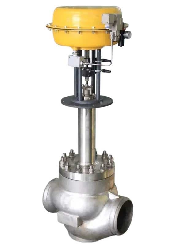
Van Điều Khiển Nhiệt Độ Thấp
Giới thiệu Van Điều Khiển Nhiệt Độ Thấp
Kích thước: 1/2" - 8" (DN15 - DN200)
Áp suất: Class 150 - 600 / PN 10-100
Tiêu chuẩn: BS 6364, MSS SP-134, IEC 60534, ISA 75
Vật liệu thân: A351 CF8M, A182 F316, A182 F55, Monel
Ghế: Kim loại với kim loại có lớp phủ Stellite
Thiết kế: Thân dạng cầu, thân van kéo dài, bộ giảm áp đa tầng hoặc cân bằng có sẵn
Bộ Truyền Động Phải Giữ Ấm
Van điều khiển trong ứng dụng nhiệt độ đông lạnh gặp hai vấn đề mà van điều khiển thông thường không gặp phải. Thứ nhất, bộ truyền động. Bộ truyền động khí nén sử dụng màng cao su và gioăng đàn hồi. Bộ truyền động điện sử dụng động cơ, bộ bánh răng và bộ định vị với các linh kiện điện tử. Không cái nào trong số này hoạt động được ở -196°C. Màng cao su đóng băng cứng—chúng nứt khi bộ truyền động cố gắng hành trình. Động cơ điện mất mô-men xoắn ở nhiệt độ đông lạnh. Bộ định vị bị trôi hoặc hỏng vì hiệu chuẩn của chúng giả định hoạt động ở nhiệt độ môi trường. Phần cổ nối dài trên van điều khiển đông lạnh thực hiện cách nhiệt tương tự như trên van cách ly—giữ khoang đệm ở nhiệt độ môi trường—nhưng nó có lợi ích thứ hai đặc thù cho van điều khiển: nó tạo khoảng cách đủ giữa thân van đông lạnh và bộ truyền động để bộ truyền động hoạt động ở nhiệt độ môi trường bình thường. Mặt bích lắp bộ truyền động trên đỉnh cổ nối dài ấm. Bộ truyền động hoạt động bình thường. Không sốc nhiệt. Không màng đông cứng. Không trôi bộ định vị.
Thứ hai: bộ tiết lưu. Van điều khiển trong dịch vụ đông lạnh tiết lưu—chúng điều chỉnh dòng chảy liên tục, không chỉ đóng mở. Việc tiết lưu đó tạo ra sụt áp qua bộ tiết lưu. Trong giảm áp đông lạnh—ví dụ giảm áp LNG từ bồn chứa sang vận chuyển—sụt áp buộc một phần chất lỏng đông lạnh bay hơi thành khí ngay lập tức. Dòng chảy hai pha—lỏng và khí trộn lẫn—ăn mòn bộ tiết lưu tiêu chuẩn chỉ trong vài tháng. Vận tốc cao, mật độ thay đổi qua đế van, và khí bay hơi mang theo các giọt lỏng va đập vào bề mặt bộ tiết lưu như phun cát.
Bộ tiết lưu đa tầng ngăn chặn hiện tượng bay hơi chớp
Bộ tiết lưu đa tầng chia tổng sụt áp thành nhiều tầng bên trong thân van thay vì dồn toàn bộ vào một vòng đế. Mỗi tầng giảm áp theo từng bước. Cường độ bay hơi chớp ở mỗi tầng thấp hơn vì bước áp suất nhỏ hơn. Dòng chảy hai pha ít mạnh hơn vì ít chất lỏng bay hơi hơn ở mỗi bước. Bộ tiết lưu tồn tại được.
Hãy nghĩ theo cách này: giảm 10 bar qua một lỗ đơn trong dịch vụ chất lỏng đông lạnh tạo ra dòng bay hơi chớp dữ dội—hầu hết chất lỏng bay hơi thành khí tại lỗ, và tia hai pha kết quả phá hủy bộ tiết lưu phía sau. Giảm cùng 10 bar qua bốn tầng—2,5 bar mỗi tầng—tạo ra bay hơi chớp nhẹ ở mỗi tầng. Chất lỏng ở mỗi áp suất trung gian vẫn chủ yếu là lỏng. Bộ tiết lưu chịu được điều kiện dòng chảy kiểm soát được ở mỗi tầng. Van điều chỉnh áp suất mà không tự phá hủy.
Bộ tiết lưu cân bằng có sẵn cho điều chỉnh đông lạnh áp suất cao. Cân bằng nghĩa là nút van có các rãnh cân bằng áp suất giúp giảm lực thủy lực ròng mà bộ truyền động phải vượt qua. Trong dịch vụ đông lạnh áp suất cao—ví dụ điều chỉnh LNG từ 50 bar xuống 5 bar—lực không cân bằng trên nút van sẽ đòi hỏi bộ truyền động quá khổ. Bộ tiết lưu cân bằng cắt giảm lực đó để bộ truyền động kích thước tiêu chuẩn xử lý việc điều chỉnh mà không cần nguồn khí hoặc công suất động cơ quá mức.
Van điều khiển đông lạnh sử dụng thân van dạng cầu, không phải thân van bi. Hình dạng thân van cầu cho bạn đường dòng chảy phù hợp cho tiết lưu—chất lỏng vào thân, chuyển hướng qua vòng đế và nút van, và thoát ra với sụt áp được kiểm soát. Hình dạng van bi không điều chỉnh tốt—đường dòng chảy về cơ bản là hình trụ thẳng với vật cản xoay được. Bạn có thể tiết lưu van bi một chút, nhưng mài mòn đế nhanh và đặc tính dòng chảy phi tuyến.
Van tiết lưu dẫn hướng bằng lồng giữ cho nút van nằm chính giữa lồng trong suốt quá trình di chuyển – phù hợp hơn cho các ứng dụng lưu lượng cao, nơi độ ổn định của nút van rất quan trọng. Van tiết lưu dẫn hướng bằng thân van dẫn hướng nút van từ khớp nối thân van – cấu tạo đơn giản hơn, phù hợp với kích thước nhỏ hơn và lưu lượng thấp hơn. Cả hai loại đều có lớp phủ Stellite trên bề mặt tiếp xúc. Stellite có khả năng chống lại tác động ăn mòn của dòng chảy hai pha ở nhiệt độ cực thấp tốt hơn so với thép không gỉ trần, kéo dài tuổi thọ của van tiết lưu trong điều kiện hoạt động nhanh.
Các chi tiết kỹ thuật quan trọng
Lựa chọn vật liệu bộ tiết lưu phụ thuộc vào sụt áp và cường độ bay hơi chớp của bạn. Lớp phủ Stellite trên bộ tiết lưu thép không gỉ xử lý bay hơi chớp đông lạnh ở mức trung bình—sụt áp dưới 5 bar mỗi tầng, tỷ lệ bay hơi dưới 15%. Cường độ bay hơi chớp cao hơn đòi hỏi vật liệu bộ tiết lưu cứng hơn—lớp phủ Inconel, miếng chèn cacbua vonfram, hoặc bộ tiết lưu toàn phần bằng Monel cho dịch vụ khắc nghiệt. Đừng chọn Stellite cho mọi thứ. Nó đắt hơn thép không gỉ trần và nếu ứng dụng của bạn không cần, bạn đang lãng phí tiền. Nhưng nếu ứng dụng của bạn cần và bạn chọn thép không gỉ trần, bạn sẽ phải thay bộ...
Thông Số Kỹ Thuật
| Pressure Class | Class150-900 |
| Design Standard | BS 6364,ISO 10497,ISO 28921 |
| Body Materials | LCC, LCB, CF8, CF8M, CF8C |
Tải xuống sản phẩm
| Lớp Áp Suất | Class150-900 |
| Tiêu Chuẩn Thiết Kế | BS 6364,ISO 10497,ISO 28921 |
| Vật Liệu Thân Van | LCC, LCB, CF8, CF8M, CF8C |
Cần Báo Giá?
Contact our engineering team for pricing and technical support on Van Điều Khiển Nhiệt Độ Thấp.
Request a QuoteTìm Kiếm Thêm Giải Pháp?
Khám phá dải sản phẩm được thiết kế cho thách thức ngành của bạn.
Ball Valves
FLOWKS offers floating ball valve, trunnion mounted ball valve and top entry ball valve for oil & gas, petrochemical and power generation. Designed per API 6D, API 608 and ASME B16.34.
DBB Valves
FLOWKS Double Block & Bleed (DBB) valves provide dual isolation with bleed verification in a single compact body. Replacing traditional multi-valve installations, FLOWKS DBB valves reduce weight, space and potential leak paths. Available in bolted bonnet, all-welded and expanding gate designs per API 6D and API 607.
Gate Valves
FLOWKS gate valves for isolation service in piping systems. Flexible wedge, solid wedge, slab and expanding gate designs per API 600, API 602 and ASME B16.34.
Globe Valves
FLOWKS globe valves for throttling and isolation. Standard, angle, Y-pattern and bellows seal configurations per API 602 and BS 1868.