Van DBB Kiểu Kim Bích-Vít
Giới thiệu Van DBB Kiểu Kim Bích-Vít
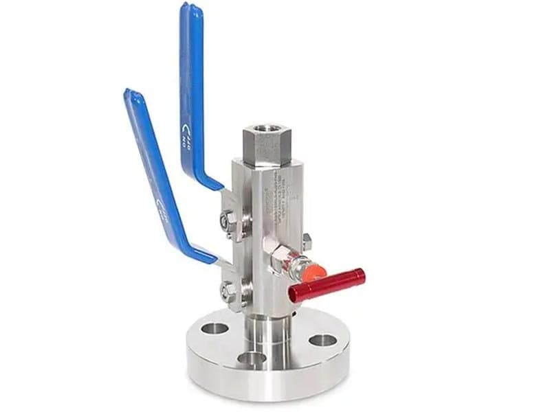
Thông số kỹ thuật nhanh 1/2" - 1" (DN15 - DN25) lên đến 10.000 psi (tương đương Class 150 - 2500) API 6D, API 607, ASME B16.34, ISO 15848 A182 F316, A182 F51, A182 F53 PTFE, PEEK, kim loại-kim loại (Stellite 6) Kết nối mặt bích phía quy trình + kết nối ren (NPT) phía thiết bị đo, van DBB dạng kim với thân compact, chặn kép và xả khí với một cổng xả duy nhất
Một đầu mặt bích, một đầu ren——Nơi đường ống dùng mặt bích nhưng thiết bị đo dùng ren
Đường ống quy trình tại điểm kết nối thiết bị đo thường có van cách ly mặt bích ở phía đường ống và kết nối ren (NPT) ở phía đồng hồ hoặc bộ truyền tín hiệu——tiêu chuẩn đường ống yêu cầu kết nối mặt bích cho đường kính trên 1" để đảm bảo tính toàn vẹn kết cấu và khả năng bảo trì, nhưng kết nối thiết bị đo (đồng hồ, bộ truyền tín hiệu, công tắc áp suất) hầu như luôn là ren 1/2" NPT vì thiết bị đo không có kết nối mặt bích. Sự không khớp đó——một bên mặt bích, một bên ren——chính xác là điều van này giải quyết. Kết nối phía quy trình (thượng nguồn) là đầu mặt bích (RF hoặc RTJ theo ASME B16.5) bắt bu-lông trực tiếp vào mặt bích đường ống. Kết nối phía thiết bị đo (hạ nguồn) là cổng ren NPT mà đồng hồ hoặc bộ truyền tín hiệu vặn trực tiếp vào. Hai ghế chặn và khoang xả nằm giữa kết nối mặt bích thượng nguồn và kết nối ren hạ nguồn——chức năng cách ly DBB trải dài toàn bộ đường dòng chảy từ giao diện mặt bích đường ống đến giao diện ren thiết bị đo, không có phụ kiện bổ sung, bộ chuyển đổi hoặc điểm rò rỉ kết nối trung gian nào giữa chúng.
Nếu không có cấu hình mặt bích-ra-ren này, người lắp đặt phải ghép nối một van cách ly mặt bích, một phụ kiện giảm (bộ chuyển đổi mặt bích-ra-ren) và một van xả riêng biệt——ba thành phần với hai điểm kết nối trung gian (mặt bích-bộ chuyển đổi, bộ chuyển đổi-thiết bị đo) đều là các đường rò rỉ ngoài tiềm ẩn. Mỗi kết nối trung gian thêm một gioăng hoặc vòng đệm ren phải được bảo dưỡng độc lập. Van DBB dạng kim mặt bích-ra-ren loại bỏ cả hai điểm kết nối trung gian——đầu mặt bích bắt trực tiếp vào đường ống, đầu ren nhận trực tiếp thiết bị đo, và cách ly DBB nằm bên trong thân van đơn giữa chúng. Không có bộ chuyển đổi. Không có phụ kiện thêm. Không có đường rò rỉ kết nối trung gian. Một thân van duy nhất bao trùm toàn bộ sự không khớp kết nối.
Dạng kim——Thân compact cho các điểm lấy tín hiệu thiết bị đo áp suất cao
Chỉ định dạng kim có nghĩa là các ghế chặn là bộ phận van kim thay vì bộ phận van bi——một nút kim côn khớp vào vòng ghế hình côn tương ứng, thay vì một bi xoay làm kín với các vòng ghế phẳng hoặc có đường viền. Bộ phận kim có hai ưu điểm thực tế ở kích thước nhỏ và áp suất cao:
Thứ nhất: hình dạng đế van kim và hình nón tạo ra sự kín khít dần dần — kim sẽ ăn sâu hơn vào hình nón khi lực đóng tăng lên, tạo ra một lớp kín tiếp xúc theo đường thẳng và càng siết chặt hơn khi mô-men xoắn trục van tăng thêm. Hành vi ăn khớp dần dần này mang lại cho van kim một lợi thế cơ học ở áp suất cao, nơi mà các đế van bi (dựa vào sự tiếp xúc bề mặt với bề mặt ở một hình dạng đế xác định) có thể gặp khó khăn trong việc duy trì sự kín hoàn toàn ở áp suất trên cấp 1500. Hình dạng côn của kim tạo ra hiệu ứng nêm — bạn càng tác dụng mô-men xoắn đóng lớn, kim càng ăn sâu vào hình nón, và lớp kín càng chặt hơn thay vì đạt đến giới hạn được xác định bởi sự biến dạng đàn hồi của đế.
Thứ hai: hình dạng compact của bộ phận kim nằm gọn trong thân van nhỏ hơn thân van bi ở cùng kích thước lỗ——cụm kim (trục, nút côn, ghế côn) chiếm thể tích bên trong ít hơn cụm bi (bi, hai vòng ghế, chốt trục) ở lỗ 1/2". Hình dạng compact đó giữ kích thước tổng thể thân van ngắn hơn và nhẹ hơn——rất quan trọng cho các lắp đặt thiết bị đo nơi không gian phân bổ tại điểm lấy tín hiệu đường ống bị hạn chế, và nơi trọng lượng trên kết nối mặt bích phải nằm trong khả năng chịu lực kết cấu của mặt bích.
Hai ghế chặn trong van DBB dạng kim là hai cụm van kim độc lập——một kim thượng nguồn (phía quy trình) và một kim hạ nguồn (phía thiết bị đo), mỗi kim có trục, ghế côn và tay vận hành riêng. Cổng xả nằm giữa hai ghế kim——một van kim thứ ba, nhỏ hơn, xả khoang giữa hai kim chặn. Ba trục, ba tay vận hành, một thân van. Mỗi kim vận hành độc lập——đóng kim thượng nguồn trước, mở van xả để kiểm tra về không, sau đó đóng kim hạ nguồn. Trình tự giống như bất kỳ thao tác DBB nào, nhưng cơ chế ngồi là kim-và-côn thay vì bi-và-vòng.
Hai kim và một van xả——Làm kín độc lập, kiểm tra độc lập
Kim thượng nguồn chặn áp suất quy trình từ kết nối mặt bích đường ống. Kim hạ nguồn chặn bất kỳ áp suất nào có thể rò rỉ qua kim thượng nguồn không đến được kết nối ren thiết bị đo. Van xả xả khoang giữa hai kim chặn ra khí quyển hoặc cống kín. Cùng logic kiểm tra DBB: đóng cả hai kim chặn, mở van xả, kiểm tra áp suất bằng không tại cổng xả——bằng không xác nhận cả hai kim đang giữ kín. Áp suất quy trình tại cổng xả cho thấy sự cố kim thượng nguồn. Áp suất tại kết nối thiết bị đo cho thấy sự cố kim hạ nguồn....
Thông Số Kỹ Thuật
| Size Range | 1/2"-4" |
| Pressure Class | Class 150 - 2500 |
| Design Standard | EEMUA PUB NO182 |
| Body Materials | A105、SS304、SS316、F51, F55, F53, Hastelloy C、Monel 400 |
| Parent Standards | API 6D, API 607, API 608, ASME B16.34, ISO 15848 |
| Parent Size Range | 2" - 24" |
| Parent Pressure Class | Class 150 - 1500 |
Tải xuống sản phẩm
| Phạm Vi Cỡ | 1/2"-4" |
| Lớp Áp Suất | Class 150 - 2500 |
| Tiêu Chuẩn Thiết Kế | EEMUA PUB NO182 |
| Vật Liệu Thân Van | A105、SS304、SS316、F51, F55, F53, Hastelloy C、Monel 400 |
Cần Báo Giá?
Contact our engineering team for pricing and technical support on Van DBB Kiểu Kim Bích-Vít.
Request a QuoteTìm Kiếm Thêm Giải Pháp?
Khám phá dải sản phẩm được thiết kế cho thách thức ngành của bạn.
Ball Valves
FLOWKS offers floating ball valve, trunnion mounted ball valve and top entry ball valve for oil & gas, petrochemical and power generation. Designed per API 6D, API 608 and ASME B16.34.
Gate Valves
FLOWKS gate valves for isolation service in piping systems. Flexible wedge, solid wedge, slab and expanding gate designs per API 600, API 602 and ASME B16.34.
Globe Valves
FLOWKS globe valves for throttling and isolation. Standard, angle, Y-pattern and bellows seal configurations per API 602 and BS 1868.
Check Valves
FLOWKS check valves prevent reverse flow. Dual plate, swing, tilting disc and lift check designs per API 594 and BS 1868.