products.productRange
مجموعه کامل شیرهای صنعتی برای تمامی کاربردها.
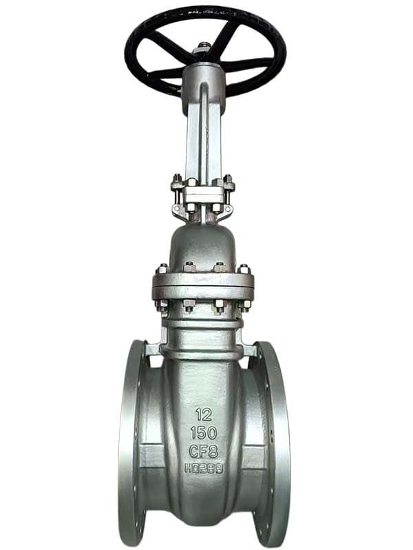
شیر کشوی دستگیرهای
درباره شیر کشویی دستی سایز: 2" - 24" (DN50 - DN600) فشار: کلاس 150 - 600 / PN 10-100 استاندارد: API 600، ASME B16.34، ASME B16.10، ASME B16.5 مواد بدنه: A216 WCB، A351 CF8M، A351 CF8 گوهای: گوهای توپر (ریختهگری یکپارچه) ساقه: ساقه بالارونده OS&Y بونیت: بونیت پیچی اتصالات: فلنجی (ASME B16.5 RF یا RTJ) شیری که همهجا میبینید از هر پالایشگاه، هر کارخانه پتروشیمی، هر نیروگاه عبور کنید — شیرهای کشویی روی لولهکشی را بشمارید. بیشتر آنها دقیقاً شبیه این یکی هستند. گوهای توپر. ساقه بالارونده. بونیت پیچی. چرخ دستی در بالا. این پیکربندی پیشرفتهترین طراحی شیر کشویی نیست و بهترین انتخاب برای هر شرایط کاری نیست. اما همانی است که بارها و بارها مشخص میشود چون سه چیز مهمتر از پیچیدگی هستند: عملکرد اثباتشده، در دسترس بودن و هزینه. به یک شیر ایزوله روی خط آب کلاس 150 نیاز دارید — این همان است. باید بخشی از لولهکشی نفت کلاس 300 را برای تعمیرات مسدود کنید — همان شیر. بخار زیر 350°F، نقاط قطع فرآیند عمومی، هدرهای سرویس — همه با شیر کشویی دستی گوهای توپر کار میکنند. این اسب کار است، نه اسب اصیل. چرا ساقه بالارونده همهچیز را به شما میگوید ساقه OS&Y یک کار انجام میدهد که مهندسان در میدان از آن قدردانی میکنند — موقعیت شیر را بدون هیچ نشانگر، بازخورد محرک یا برچسبی نشان میدهد. ساقه بالای چرخ دستی یعنی باز. ساقه در سطح چرخ دستی یعنی بسته. میتوانید ساعت 6 صبح در امتداد قفسه لوله قدم بزنید، به ارتفاع ساقه هر شیر نگاه کنید و وضعیت خط را قبل از بررسی نمایشگر اتاق کنترل بدانید. این نمایش بصری دلیل تسلط OS&Y بر طراحیهای ساقه بالارونده با چرخ دستی بالارونده است که در آن چرخ دستی با باز شدن شیر از ساقه بالا میرود. وقتی چرخ دستی با ساقه حرکت میکند، نمیتوانید موقعیت ساقه را بهطور مستقل تشخیص دهید — چرخ ممکن است نیمهبالا باشد و هیچ راهی برای تشخیص یکچهارم باز از کاملاً باز نداشته باشید. OS&Y چرخ دستی را از حرکت ساقه جدا میکند. چرخ در جای خود میماند، ساقه از میان آن حرکت میکند. واضح، بدون ابهام، بدون نیاز به تفسیر. خود چرخ دستی سادهترین عملگری است که میتوانید روی شیر نصب کنید. بدون منبع هوا، بدون برق، بدون براکت نصب محرک. چرخ را میگیرید و میچرخانید. مهره ساقه داخل یوک میچرخد، ساقه از داخل مهره رزوه میشود و گوهای بالا یا پایین حرکت میکند. عملکرد مکانیکی مستقیم — همان نوعی که وقتی برق قطع میشود و کمپرسور هوای ابزار دقیق از کار میافتد، همچنان کار میکند. کاری که گوهای توپر نمیتواند انجام دهد محدودیت این است، و به اندازه کافی مهم است که قبل از مشخصکردن این شیر برای سرویس بخار یا چرخههای دمای بالا به آن فکر کنید. گوه توپُر یک تکه فلز ریختهگریشده است — بدون انعطاف، بدون جبران انبساط. وقتی بدنه شیر گرم میشود، حلقههای نشیمن به سمت بیرون منبسط میشوند چون بخشی از بدنه هستند. گوه نیز منبسط میشود، اما اگر سطوح نشیمن بدنه و گوه از مواد یا روکشهای متفاوت استفاده کنند، نرخ انبساط همخوانی ندارد. نشیمنهای بدنه بیشتر از آنچه گوه بتواند تحمل کند باز میشوند و گوه بین آنها گیر میکند. شیر بسته نمیشود، یا بسته میشود اما بدون اعمال نیرو به فرمان تا شکستن قطعهای باز نمیشود. این گیرکردن در دماهای متوسط رخ نمیدهد چون اختلاف انبساط کوچک است — چند هزارم اینچ که تلورانسهای ماشینکاری آن را جذب میکنند. اما در دماهای بخار بالای 350 درجه فارنهایت، یا در سرویسهایی که شیر بهطور مکرر بین گرم و سرد چرخه میکند، عدم تطابق انبساط تجمعی از فاصله بین گوه و نشیمنها فراتر میرود. آنجاست که به گوه انعطافپذیر نیاز دارید — هر بال بهطور مستقل منحرف میشود تا انبساط تفاضلی را جبران کند. برای آب، روغن، گاز و بخار با دمای متوسط در کلاس 150-300، گوه توپُر شرایط سرویس را بدون مشکل مدیریت میکند. اکثر نقاط ایزوله در یک کارخانه فرآیندی معمولی در این دسته قرار میگیرند، به همین دلیل این شیر مشخصات پیشفرض باقی میماند. Bonnet پیچشده — اثباتشده و قابل نگهداری Bonnet پیچشده بست استاندارد برای کلاس 150-600 است. Bonnet با یک واشر بین آنها به بدنه پیچ میشود. وقتی نیاز به دسترسی به قطعات داخلی دارید — تعویض حلقههای نشیمن، ماشینکاری مجدد سطوح نشیمن گوه، تعویض packing ساقه — پیچهای Bonnet را باز میکنید، آن را بلند میکنید و شیر برای تعمیر و نگهداری باز است. روش ساده، ابزار استاندارد، بدون نیاز به آموزش ویژه. واشر بین Bonnet و بدنه، آببند مرز فشار است. تحت پیشبار پیچ فشرده میشود و آببند را در کل محدوده فشار کاری حفظ میکند. در کلاس 150-300، نیروهای پیچ قابل مدیریت هستند و طراحی واشر ساده است. در کلاس 600، پیچها بزرگتر میشوند و واشر به فشردهسازی بیشتری نیاز دارد، اما طراحی همچنان کار میکند — فقط نیاز به گشتاور دقیق پیچ در هنگام مونتاژ دارد. پاسخ: توصیه نمیشود. گوه توپُر عدم تطابق انبساط حرارتی بین نشیمنهای بدنه و گوه را جبران نمیکند. در دماهای بالای 350 درجه فارنهایت، گوه میتواند در نشیمنها گیر کند. برای سرویس بخار و چرخههای دمای بالا از شیر کشویی با گوه انعطافپذیر استفاده کنید. پاسخ: به ساقه نگاه کنید. OS&Y با ساقه بالارونده — ساقه بالای فرمان یعنی شیر باز است. ساقه در سطح فرمان پایین یعنی بسته. نیازی به نشانگر موقعیت نیست. پاسخ: گوه توپُر یک قطعه صلب واحد است. محکم مینشیند و در دماهای متوسط بهطور قابل اعتماد کار میکند. گوه انعطافپذیر دارای یک توپی مرکزی با دو بال قابل انحراف است که انبساط حرارتی و تنش لوله را جذب میکنند. گوههای انعطافپذیر 5-10 درصد گرانتر هستند اما از گیرکردن در سرویس دمای بالا جلوگیری میکنند. پاسخ: Bonnet پیچشده طراحی استاندارد و اثباتشده برای کلاس 150-600 است. برای تعمیر و...
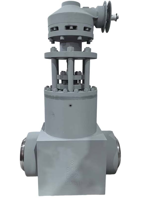
شیر کشوی گوه خودآببند فولاد فورج
سایز: 2" - 12" (DN50 - DN300) فشار: کلاس 600 - 2500 / PN 100-420 استاندارد: API 602، ASME B16.34، مخصوص تولیدکننده برای Bonnet فشار-آببند مواد بدنه: A182 F22، A182 F91، A182 F316، A182 F304 (همگی آهنگریشده) گوه: گوه انعطافپذیر Bonnet: فشار-آببند (خودآببند) ساقه: OS&Y بالارونده با فرمان اتصالات: جوش لببهلب یا فلنجی دو چیز که همهچیز را در فشار بالا تغییر میدهند این شیر دو مشکل را حل میکند که بالای کلاس 600 ظاهر میشوند — مشکلاتی که شیرهای کشویی با بدنه ریختهگری و Bonnet پیچشده نمیتوانند مدیریت کنند. اول، آببند Bonnet. دوم، یکپارچگی بدنه. با هم، این شیر را به مشخصات استاندارد برای بخار اصلی نیروگاه، ایزولاسیون reheater، آب تغذیه فشار بالا و سرویس فشار بالای پتروشیمی تبدیل میکنند، جایی که شرایط عملیاتی فراتر از آن چیزی است که یک شیر کشویی استاندارد میتواند بهطور ایمن مهار کند. Bonnet فشار-آببند — آببندی که تحت فشار قویتر میشود در کلاس 150-300، Bonnet پیچشده بهخوبی کار میکند. فشار داخلی Bonnet را به سمت بالا هل میدهد و پیچهای Bonnet آن را در برابر واشر نگه میدارند. نیروهای قابل مدیریت، اندازه پیچهای معقول، مونتاژ ساده. در کلاس 600 و بالاتر، نیروی رو به بالا روی Bonnet عظیم میشود. پیچها باید حجیم باشند — به گل میخهای 2 اینچی با مهرههای هیدرولیکی کشیدهشده در شیرهای کلاس 1500 و 2500 فکر کنید. آن سختافزار گران است، تنظیم گشتاور صحیح آن در محل دشوار است و هر بار که نیاز به باز کردن شیر دارید مشکلات تعمیراتی ایجاد میکند. Bonnet فشار-آببند مشکل پیچ را کاملاً حذف میکند. بهجای پیچهایی که Bonnet را در برابر بدنه نگه میدارند، فشار خط داخلی کار را انجام میدهد. در داخل اتصال Bonnet به بدنه، یک حلقه آببند قطعهای بین دامن Bonnet و سوراخ بدنه قرار دارد. وقتی فشار وارد شیر میشود، به سمت بالا به Bonnet فشار میآورد و همزمان حلقه آببند را در برابر دیواره بدنه فشرده میکند. فشار بالاتر آببند را محکمتر فشرده میکند. در فشار کاری کلاس 2500، آن حلقه آببند چنان محکم بین Bonnet و بدنه فشرده میشود که نشتی از اتصال از نظر فیزیکی غیرممکن میشود — فشاری که میتواند باعث نشتی شود همان فشاری است که نیروی آببندی را ایجاد میکند. درپوش توسط یک حلقه نگهدارنده یا اتصال رزوهای در جای خود نگه داشته میشود، نه توسط پیچهایی که در بیرون میبینید. آن پیچها فقط یک هدف دارند — نشستن در فشار پایین هنگام راهاندازی، زمانی که فشار خط به آستانهای نرسیده که حلقه آببند به طور مؤثر فشرده شود. وقتی شیر به فشار کاری رسید، آن پیچها بدون بار هستند. آنها نیروی آببندی را تحمل نمیکنند. فشار خط این کار را میکند. این طراحی مزیت تعمیراتی دارد که تکنسینهای باتجربه شیرآلات فوراً آن را درک میکنند — هیچ واشر و آببندی برای تعویض وجود ندارد و هیچ روش سفتکردن پیچ برای مونتاژ مجدد لازم نیست. حلقه آببند یک قطعه فلزی است که بازرسی میشود و در صورت نیاز دوباره سنگزنی میشود. درپوش با قرار دادن آن در حفره بدنه و درگیر کردن حلقه نگهدارنده دوباره نصب میشود. وقتی فشار دوباره بالا میآید، آببندی به طور خودکار برقرار میشود. بدنه آهنگری — بدون تخلخل، بدون نشتی در کلاس 2500 بدنههای ریختهگری در کلاس 600 و پایینتر به طور قابل اعتماد کار میکنند. فرآیند ریختهگری فلز سالمی با سطوح کیفیت قابل قبول برای آن ردههای فشاری تولید میکند. اما در کلاس 600-2500، تخلخل ریختهگری به ریسکی تبدیل میشود که نمیتوانید بپذیرید. قطعات ریختهگری میتوانند حاوی حفرههای میکروسکوپی باشند — حبابهای گاز محبوس، حفرههای انقباضی، عیوب آخال — که روی سطح نامرئی هستند اما تحت بار فشاری مداوم بالا نشتی میدهند. عیب تخلخل در دیواره بدنه شیر کلاس 2500 بلافاصله وقتی شیر وارد سرویس شود نشتی میدهد. ضخامت دیواره در آن ردهها با حداقل حاشیه محاسبه میشود — فلز اضافی برای جذب حفره وجود ندارد. آهنگری مشکل تخلخل را کاملاً از بین میبرد. فرآیند آهنگری فلز را تحت فشار عظیم فشرده میکند، هر حفرهای را میبندد و ساختار دانهها را در یک ماتریس متراکم و یکنواخت همراستا میکند. بدنه آهنگری هیچ حفره داخلی، تخلخل گازی یا عیوب انقباضی ندارد. فلز در تمام سطح مقطع دیواره یکپارچه است. در کلاس 600-2500، آن یکپارچگی بدنه جامد دلیلی است که ساخت آهنگری استاندارد است — نه یک گزینه ارتقا، بلکه الزام پایه. آلیاژهای آهنگری این شیر بر اساس شرایط سرویس خاص انتخاب میشوند. A182 F22 (2.25% Cr-1% Mo) برای سرویس دمای بالا که مقاومت خزشی اهمیت دارد. A182 F91 (9% Cr-1% Mo-V) برای بالاترین دماهای کاری — خطوط بخار اصلی و ریهیتر در نیروگاهها که در دمای 1000°F و بالاتر کار میکنند. افزودن وانادیوم در F91 استحکام خزشی بلندمدت برتری نسبت به F22 فراهم میکند. A182 F316 و F304 برای سرویس خورنده که شیمی فولاد ضدزنگ در برابر حمله سیال فرآیندی مقاومت میکند. گوه انعطافپذیر — الزامی در این دماها در کلاس 600-2500، دمای کاری به اندازه کافی بالا است که قفلشدگی ناشی از انبساط حرارتی با گوه جامد قطعی است — نه احتمال، بلکه قطعیت. گوه انعطافپذیر با توپی مرکزی و بالهای قابل خمش از آن قفلشدگی جلوگیری میکند. هر بال به طور مستقل با انبساط حلقه نشیمنگاه تنظیم میشود و تماس را روی هر دو نشیمنگاه بدون توجه به گرمایش نامتقارن یا نرخهای انبساط متفاوت حفظ میکند. در این سطوح فشار و دما، گوه انعطافپذیر یک ارتقای اختیاری نیست. این تنها طراحی گوهای است که کار میکند. پاسخ: درپوشهای پیچشده در کلاس 600+ به پیچهای بزرگ برای نگه داشتن درپوش در برابر فشار داخلی نیاز دارند — سختافزاری گرانقیمت که سفتکردن و نگهداری آن دشوار است. درپوشهای...
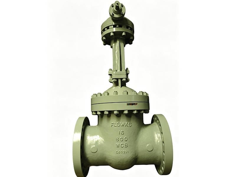
شیر کشوی گوه انعطافپذیر
سایز: 2" - 24" (DN50 - DN600) فشار: کلاس ۱۵۰ - ۶۰۰ / PN 10-100 (ریخته گری)، کلاس ۶۰۰ - ۲۵۰۰ / PN 100-420 (آهنگری، آب بندی تحت فشار) استاندارد: API 600 (ریختهگری)، API 602 (آهنگری)، ASME B16.34 مواد بدنه: A216 WCB، A351 CF8M، A351 CF8 (ریختهگری، کلاس 150-600)؛ A182 F22/F91/F316/F304 (آهنگری، کلاس 600-2500) گوه: گوه انعطافپذیر — توپی مرکزی با بالهای قابل خمش درپوش: درپوش پیچشده (کلاس 150-600) یا آببند فشاری (کلاس 600-2500) میله: میله بالارونده OS&Y با چرخ دستی اتصالات: فلنجی یا جوش لب به لب گوهای که خم میشود به جای قفل شدن گوه انعطافپذیر یک مشکل خاص را حل میکند — قفلشدگی حرارتی. این یک راهحل متمرکز است، نه یک ارتقای عمومی. اگر شرایط سرویس شما باعث عدم تطابق انبساط حرارتی نمیشود، گوه جامد به همان خوبی کار میکند و هزینه کمتری دارد. اما اگر شیر شما در بخار بالای 350°F، فرآوری روغن داغ، یا هر سرویسی که دما بین گرم و سرد در هنگام راهاندازی، خاموشکردن، یا عملکرد چرخهای نوسان میکند کار میکند، گوه انعطافپذیر طراحیای است که شیر را زمانی که گوه جامد قفل میشود، عملکردی نگه میدارد. بدون این انعطافپذیری، این اتفاق میافتد: بدنه شیر گرم میشود. حلقههای نشیمن — که داخل بدنه ماشینکاری شده یا در آن قرار گرفتهاند — به دلیل اتصال حرارتی با فلز بدنه، به سمت بیرون منبسط میشوند. گوه نیز منبسط میشود، اما سطوح نشیمن روی گوه ممکن است جنس روکش متفاوتی نسبت به نشیمنهای بدنه داشته باشند. روکش استیل ضدزنگ روی نشیمنهای فولاد کربنی، روکش سخت استلایت روی نشیمنهای آلیاژی — جنس روکش ضریب انبساط حرارتی متفاوتی نسبت به فلز پایه دارد. گوه با یک نرخ رشد میکند و حلقههای نشیمن با نرخ دیگری باز میشوند. وقتی نشیمنها بازتر از حدی شوند که گوه بتواند به آنها برسد، گوه در فاصله ایجادشده فرو میرود و نمیتواند آببندی کند. وقتی نشیمنها بازتر از حدی شوند که گوه جا بگیرد، گوه گیر میکند و اصلاً نمیتواند حرکت کند. گوه انعطافپذیر از هر دو خرابی جلوگیری میکند. توپی مرکزی دو بخش بال را که از توپی نازکتر هستند به هم متصل میکند - این کاهش ضخامت به هر بال مقدار کمی انحراف فنر میدهد. هر بال میتواند به طور مستقل به سمت حلقه نشیمنگاه مربوطه خود حدود 0.5 تا 1 میلیمتر حرکت کند یا از آن دور شود. هنگامی که حلقه نشیمنگاه سمت چپ بیشتر از سمت راست منبسط میشود (گرمایش نامتقارن ناشی از توزیع ناهموار بخار یا جهت لوله)، بال چپ به سمت بیرون منحرف میشود تا نشیمنگاه منبسط شده را دنبال کند در حالی که بال راست در موقعیت خود باقی میماند. توپی دو بال را به صورت مکانیکی در کنار هم نگه میدارد، اما بالها به طور محکم به یکدیگر قفل نشدهاند - آنها به طور مستقل در محدوده انحراف خم میشوند. همین انعطافپذیری، تنش لوله را نیز مدیریت میکند. وقتی سیستم لولهکشی، بدنه شیر را تحت نیروهای خمشی ناشی از انبساط حرارتی لولهها قرار میدهد، بدنه کمی کج میشود. حلقههای نشیمنگاه از تراز موازی اولیه خود خارج میشوند. یک گوه محکم با این کجی مقابله میکند - سعی میکند در مقابل حلقههایی که دیگر موازی نیستند، قرار گیرد و نمیتواند با آن مطابقت داشته باشد. بالهای انعطافپذیر با هندسه کجشده تنظیم میشوند و هر بال کمی زاویه میگیرد تا تماس نشیمنگاه را در سراسر عرض کامل سطح نشیمنگاه حفظ کند. زمان نیاز به آن — و زمان عدم نیاز سرویس بخار بالای ۳۵۰ درجه فارنهایت — بله، گوه انعطافپذیر را مشخص کنید. این کاربرد اصلی است و جایی است که خطر قفل حرارتی بالاترین میزان را دارد. نیروگاههای برق، توزیع بخار صنعتی، سیستمهای گرمایش فرآیندی — همه آنها با شیرهای کشویی گوه انعطافپذیر کار میکنند، زیرا دمای عملیاتی و چرخههای دمایی در هنگام راهاندازی شرایط انبساطی ایجاد میکنند که گوههای توپر نمیتوانند مدیریت کنند. فرآوری نفت و گاز داغ که دمای سیال از ۳۵۰ درجه فارنهایت فراتر میرود — بله. خطوط فرآیند پالایشگاه، سیستمهای گرمایش نفت خام، فرآوری شیمیایی با دمای بالا — همان عدم تطابق انبساط صدق میکند، حتی اگر سیال بخار نباشد. کارکرد چرخشی که در آن شیر به طور مکرر از دمای محیط به دمای عملیاتی تغییر میکند - بله. چرخههای راهاندازی و خاموش شدن، بدترین شرایط را برای گوههای جامد ایجاد میکنند زیرا اختلاف انبساط در طول هر چرخه جهت را تغییر میدهد. گوه در دمای عملیاتی قرار میگیرد، سپس شیر خنک میشود و نشیمنگاهها منقبض میشوند. اگر گوه در حین خنک شدن در حالت بسته باقی بماند، میتواند به نشیمنگاههای منقبض شده بچسبد. گوه انعطافپذیر بدون از دست دادن تماس نشیمنگاه، این انقباض را تحمل میکند. سرویس عمومی آب، نفت و گاز در دماهای متوسط زیر ۳۵۰ درجه فارنهایت — به گوه انعطافپذیر نیازی ندارید. گوه توپر این شرایط را بدون قفل شدن مدیریت میکند. اختلاف هزینه بین گوه توپر و انعطافپذیر در اندازههای ریختهگری حداقل است — حدود ۵-۱۰٪ از قیمت شیر. اما اگر شرایط سرویس آن را ایجاب نکند، آن هزینه اضافی غیرضروری است. گوه انعطافپذیر را زمانی مشخص کنید که سرویس آن را میطلبد، نه بهعنوان ارتقای پیشفرض. در اندازههای آهنگری برای کلاس ۶۰۰-۲۵۰۰، گوه انعطافپذیر پیشفرض است — نه یک گزینه. قفل حرارتی در آن دماها و فشارهای عملیاتی ریسکی نیست که برای صرفهجویی در هزینه گوه بپذیرید. ریختهگری یا آهنگری — بدنه با فشار هماهنگ است این شیر در دو ساختار بدنه عرضه میشود که با محدوده فشار مطابقت دارند. کلاس ۱۵۰-۶۰۰ از بدنههای ریختهگری استفاده میکند — A216 WCB، A351 CF8M، A351 CF8 — با بونیت پیچی. مواد استاندارد، طراحی بونیت استاندارد، اثباتشده در آن رتبهبندیها. کلاس ۶۰۰-۲۵۰۰ از بدنههای آهنگری استفاده میکند — A182 F22، F91، F316، F304 — با...
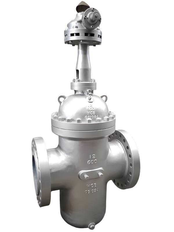
شیر کشوی تخت
اندازه: ۲ اینچ تا ۴۸ اینچ (DN50 تا DN1200) فشار: کلاس ۱۵۰ تا ۹۰۰ / PN 10-150 استاندارد: API 6D، مخصوص تولیدکننده برای طراحی گیت تخت/اسلب جنس بدنه: A216 WCB، A351 CF8M، فولاد آهنگری (A182 F316/F22)، بدنه تمامجوشی موجود است گیت: گیت اسلب تخت (تکصفحهای) یا گیت انبساطی (سازوکار آببندی مکانیکی دوصفحهای) نشیمنگاه: فلزبهفلز (حلقههای نشیمن موازی) یا نرم (درج الاستومر/PTFE) بوننت: بوننت پیچومهرهای یا فشارمحور (Pressure-Seal) طراحی: عبور کامل تمامبُرد (Through-Conduit Full-Bore) — گیت دارای سوراخی به اندازه بُرد است که هنگام باز بودن با لوله همتراز میشود تمامبُرد یعنی پیگ از داخل عبور میکند شیرهای گیت تخت — که به آنها شیرهای گیت اسلب عبور کامل نیز گفته میشود — به دلیلی وجود دارند که شیرهای گیت گوهای نمیتوانند آن را حل کنند. وقتی شیر باز است، صفحه گیت سوراخی دارد که دقیقاً با قطر بُرد لوله مطابقت دارد. آن سوراخ با بُرد خط لوله همتراز میشود و گیت بخشی از مسیر جریان بدون مانع میگردد. هیچ کاهشی در سطح مقطع وجود ندارد، هیچ ناحیه گود و فرورفتهای که زباله در آن جمع شود نیست، هیچ محدودیت جریانی که سالها در عملیات مداوم هزینه انرژی پمپاژ تحمیل کند وجود ندارد. همین گذرگاه تمامبُرد دلیل تسلط شیرهای گیت تخت بر جداسازی خط لوله است. خطوط لوله با فرستادن پیگها از داخل خط بازرسی میشوند — ابزارهای بازرسی، ابزارهای تمیزکاری، پیگهای هوشمند که ضخامت دیواره را اندازهگیری میکنند و خوردگی را تشخیص میدهند. پیگ با فشار جریان محصول با سرعت خط از داخل بُرد لوله حرکت میکند. اگر شیر گیت حتی کمی بُرد را محدود کند، پیگ به مانع برخورد کرده و میایستد. یا آسیب میبیند. یا داخل بدنه شیر گیر میکند، که نوعی مشکل است که یک بخش خط لوله را برای روزها از کار میاندازد و صدها هزار دلار از دست دادن ظرفیت انتقال هزینه دارد. شیرهای گیت گوهای توپر در برخی اندازهها بدنه با بُرد کاهشیافته دارند — بُرد داخل بدنه کوچکتر از قطر اسمی لوله است. این کاهش برای بیشتر جداسازیهای فرآیندی که فقط جریان را مسدود میکنید و پیگ اجرا نمیکنید، مشکلی ایجاد نمیکند. اما برای سرویس خط لوله، بُرد کاهشیافته غیرقابل قبول است. شیر گیت تخت عبور کامل در حالت باز صفر کاهش بُرد دارد. پیگ از داخل بدنه شیر عبور میکند انگار که شیر وجود ندارد. قطر کامل، سطح جریان کامل، بدون هیچ مانعی. دلیل دوم اهمیت تمامبُرد — خطوط لوله نفت خام و گاز طبیعی سالها بهطور مداوم کار میکنند. افت فشار در یک شیر نیمهمحدود در طول آن دوره عملیاتی هزینه انرژی پمپاژ را انباشته میکند. یک شیر گیت با بُرد کاهشیافته روی خط انتقال گاز طبیعی ۳۶ اینچ ممکن است افت فشار ۲ تا ۳ psi در دبیهای عملیاتی ایجاد کند. این زیاد به نظر نمیرسد، اما در یک خط لوله ۲۰۰ مایلی با دهها شیر جداسازی، افت فشار تجمعی هزینه سوخت کمپرسور را اضافه میکند که سالانه به شش رقم میرسد. گیتهای تخت عبور کامل این محدودیت را کاملاً حذف میکنند. گیت اسلب در برابر گیت انبساطی — دو روش آببندی دریچهی صفحهای یک صفحهی تخت تکی است که به صورت عمودی بین دو حلقهی نشیمنگاه موازی میلغزد. وقتی صفحه بین نشیمنگاهها قرار میگیرد، بخش توپر، دهانه را مسدود میکند. وقتی صفحه بالا میآید، سوراخ به اندازهی دهانه در صفحه با خط لوله همتراز میشود و جریان بدون مانع از آن عبور میکند. طراحی ساده، قطعات متحرک کم، عملکرد قابل اعتماد در سرویس خط لوله. مکانیزم آببندی برای یک دریچهی تختال به فشار خط لوله که صفحهی دریچه را به حلقهی نشیمنگاه پاییندست فشار میدهد، متکی است. نشیمنگاه بالادست با صفحه در تماس است، اما آببندی اولیه در سمت پاییندست اتفاق میافتد، جایی که فشار خط لوله، صفحه را به سطح نشیمنگاه فشار میدهد. این آببندی فعالشده با فشار در فشارهای عملیاتی عادی به خوبی کار میکند. در اختلاف فشار کم - فشار خط نزدیک به صفر در هنگام راهاندازی، یا برابرسازی فشار در شیر در طول عملیات بایپس - نیروی آببندی حداقل است و دریچهی تختال ممکن است به قطع کامل حباب دست نیابد. دریچه انبساطی آن محدودیت آببندی در فشار پایین را حل میکند. دو صفحه که توسط یک مکانیزم گوهای به هم متصل شدهاند - هنگامی که دریچه به حالت بسته پایین میآید، گوه داخلی دو صفحه را به سمت بیرون و در خلاف جهت حلقههای نشیمنگاه موازی هل میدهد. صفحات به صورت مکانیکی و مستقل از فشار خط منبسط میشوند. هنگامی که دریچه به حالت بسته کامل میرسد، هر دو صفحه توسط مکانیزم گوهای محکم به حلقههای نشیمنگاه مربوطه خود فشرده میشوند و آببندی ایجاد میکنند که برای عملکرد به فشار خط وابسته نیست. قطع حباب در هر فشاری، از جمله صفر. گیت انبساطی هزینه بیشتری دارد و پیچیدگی مکانیکی اضافه میکند — دو صفحه، سازوکار گوهای، سطوح آببندی بیشتر برای نگهداری. اما برای جداسازی خط لوله جایی که قطع جریان حباببسته یک الزام نظارتی است — خطوط انتقال گاز طبیعی، خطوط لوله مایعات خطرناک مشمول انطباق DOT — گیت انبساطی قطعیت آببندی را فراهم میکند که گیتهای اسلب در اختلاف فشار پایین یا صفر نمیتوانند تضمین کنند. نشیمنگاههای موازی - مخروطی شکل نیستند تمام طرحهای شیر دروازهای تخت از حلقههای نشیمنگاه موازی استفاده میکنند، نه نشیمنگاههای گوهای مخروطی. حلقههای نشیمنگاه با یکدیگر موازی هستند و صفحه گیت با حرکت عمودی مستقیم بین آنها میلغزد. بدون عمل گوهای، بدون سطوح نشیمنگاه زاویهدار، بدون فشار دادن گیت به داخل حفره بدنه مخروطی. هندسه نشیمنگاه موازی به این معنی است که گیت به داخل نشیمنگاهها فشرده نمیشود - بین آنها میلغزد و یا لوله را مسدود میکند یا سوراخ عبور را تراز میکند. نسخههای دارای نشیمنگاه نرم از الاستومر یا PTFE در سطوح حلقه...
مروری بر مشخصات فنی
شیرهای کشویی ایزوله میکنند — باز میشوند تا جریان کامل بدون مانع از مجرای عبور کند، یا بسته میشوند تا آن را کاملاً مسدود کنند. این شیرها برای تنظیم جریان نیستند. یک شیر کشویی نیمهباز دارای گوهای یا کشویی است که در مسیر جریان قرار میگیرد و باعث لرزش، فرسایش نشیمنگاه و نویز میشود. برای تنظیم جریان، شیر گلوب یا کنترل شیر مشخص کنید؛ برای قطع و وصل، شیر کشویی مشخص کنید. FLOWKS چهار پیکربندی شیر کشویی تولید میکند که طیف کامل اندازهها، فشارها و دماهای لولهکشی فرآیندی را پوشش میدهد. شیرهای کشویی دستی با گوهای توپر و بونیت پیچی، شیر ایزوله پیشفرض برای لولهکشی فرآیندی عمومی هستند — کلاس 150-600 در سایز 2"-24"، عملکرد دستی ساده، نمایش بصری موقعیت با ساقه بالارونده، عملکرد اثباتشده و مقرونبهصرفه. شیرهای کشویی گوهای خودآببند از فولاد آهنگری با بونیت فشار-آببند و بدنه آهنگری، یکپارچگی بدون تخلخل را در کلاس 600-2500 ارائه میدهند جایی که بونیتهای پیچی از نظر ساختاری غیرعملی میشوند و عیوب ریختهگری غیرقابل قبول است — فشار خود خط با افزایش فشار، حلقه آببند را محکمتر فشرده میکند. شیرهای کشویی با گوهای انعطافپذیر مشکل قفل حرارتی را حل میکنند — دو بخش بالی بهطور مستقل خم میشوند تا انبساط حلقه نشیمن، تنش لوله و اعوجاج بدنه را جبران کنند که در دمای بالا میتواند گوهای توپر را بین نشیمنگاههای منبسطشده گیر بیندازد. شیرهای کشویی تخت (اسلب/گیت انبساطی با مجرای عبوری) عبور کامل و بدون مانع را هنگام باز بودن فراهم میکنند — سوراخ همسایز مجرا در صفحه کشویی با خط لوله تراز میشود تا هیچ محدودیتی در جریان نباشد و امکان عبور پیگ خط لوله و حداقل افت فشار در خطوط انتقال طولانی نفت خام/گاز فراهم شود.
شیرهای کشویی FLOWKS قطع و وصل کامل را در طیف کامل اندازهها، فشارها و دماهای لولهکشی صنعتی ارائه میدهند. شیرهای کشویی دستی با گوهای توپر و بونیت پیچی، ایزوله فرآیندی عمومی را در کلاس 150-600 از 2"-24" پوشش میدهند — پیکربندی کار اصلی برای نفت و گاز، پتروشیمی، آب و سرویس بخار با دمای متوسط با نمایش بصری موقعیت ساقه بالارونده. شیرهای کشویی گوهای خودآببند از فولاد آهنگری با بونیت فشار-آببند، ایزوله فشار بالا و دمای بالا را در کلاس 600-2500 ارائه میدهند — بدنه آهنگری تخلخل ریختهگری را حذف میکند، بونیت فشار-آببند از فشار خط بهعنوان نیروی آببندی بهجای پیچهای عظیم بونیت استفاده میکند، گوهای انعطافپذیر قفل انبساط حرارتی را در دمای کاری بالای 350°F جبران میکند. شیرهای کشویی با گوهای انعطافپذیر از قفل حرارتی نشیمنگاه در سرویس بخار و دماهای چرخهای جلوگیری میکنند — هر بال بهطور مستقل خم میشود تا تماس نشیمنگاه را حفظ کند وقتی انبساط بدنه هندسه نشیمنگاه را تغییر میدهد. شیرهای کشویی تخت با طراحی مجرای عبوری، عبور کامل و بدون مانع را برای پیگ خط لوله و ایزوله با افت فشار صفر در خطوط لوله نفت خام، گاز طبیعی و محصولات از 2"-48" فراهم میکنند — گیت اسلب برای ایزوله پایه، گیت انبساطی برای قطع کاملاً آببند در فشار دیفرانسیل پایین.
دانلود محصولات
صنایع استفادهکننده از این محصول
کاربردها در بخشهای مختلف صنعتی.
Oil & Gas
Upstream, midstream and downstream valve solutions meeting API 6D, API 607 fire-safe requirements. From wellhead to refinery, FLOWKS provides reliable valve solutions for the most demanding oil and gas applications.
Power Generation
High-temperature and high-pressure valves for fossil fuel, nuclear, and renewable energy plants. FLOWKS gate valves and globe valves are proven in power generation service worldwide.
Refining
Heavy-duty valves designed for the extreme conditions of petroleum refining. FLOWKS valves handle high temperatures, corrosive media, and erosive service in refineries globally.
products.lookingMore
products.lookingMoreDesc
Ball Valves
FLOWKS offers floating ball valve, trunnion mounted ball valve and top entry ball valve for oil & gas, petrochemical and power generation. Designed per API 6D, API 608 and ASME B16.34.
DBB Valves
FLOWKS Double Block & Bleed (DBB) valves provide dual isolation with bleed verification in a single compact body. Replacing traditional multi-valve installations, FLOWKS DBB valves reduce weight, space and potential leak paths. Available in bolted bonnet, all-welded and expanding gate designs per API 6D and API 607.
Globe Valves
FLOWKS globe valves for throttling and isolation. Standard, angle, Y-pattern and bellows seal configurations per API 602 and BS 1868.
Check Valves
FLOWKS check valves prevent reverse flow. Dual plate, swing, tilting disc and lift check designs per API 594 and BS 1868.