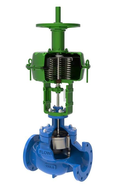
High Performance Linear Stroke Control Valve with Handwheel
About
Quick Specs Size: 1/2" - 12" (DN15 - DN300) Pressure: Class 150 - 600 Standard: IEC 60534, API 608, ASME B16.34 Body Materials: A216 WCB, A351 CF8M, A182 F316, A182 F51 Seat/Trim Materials: PTFE, PEEK, Stellite 6, 316 SS, 17-4PH SS
Design: Linear stroke, plug-type trim, pneumatic/electric actuated with integrated handwheel, equal-percentage or linear flow characteristic Same Valve, One Critical Addition
Everything about this valve——the plug and cage trim, the flow characteristics, the body materials, the pressure ratings——is identical to the standard FLOWKS high performance linear stroke control valve. What's different is the handwheel mounted on the actuator assembly. That handwheel gives you manual control over the valve position when the actuator can't do the job——air supply failure, power outage, actuator maintenance, or commissioning and startup sequences where you need to set the valve to a specific position by hand before the control system takes over. On a process line running critical flow, losing valve control means losing process control. The handwheel isn't a backup for lazy days——it's emergency access to the valve stem when the automated system can't reach it.
When the Handwheel Gets Used——and It's Not Just During Emergencies
Plant startup is where the handwheel earns its value first. Before the control system is live, before the instrument air lines are pressurized, before the DCS has its loop configurations loaded——the valve needs to be positioned manually to establish initial flow conditions. An operator walks up, turns the handwheel, sets the valve to the startup position the process engineer specified, and holds it there until the automated system is ready to take command. Without the handwheel, you'd need to pressurize the air system first, stroke the valve through the actuator, and verify position through the control room——a longer sequence that delays startup and adds coordination complexity.
Commissioning and loop tuning is the second scenario. When the instrument team is calibrating the control loop, they need to verify valve response at specific travel positions——10%, 25%, 50%, 75%, full open. Walking the valve through those positions manually with the handwheel is faster and more intuitive than commanding each step through the DCS, especially when the loop isn't yet configured and the actuator is responding to ad-hoc signals rather than a tuned control algorithm. The handwheel lets the commissioning team feel the valve's mechanical response directly——you can sense stiffness, detect plug-seat contact, verify that the stem moves freely through the full travel range without binding or hesitation. That hands-on verification is something remote actuator control can't provide.
Actuator maintenance is the third. When the pneumatic actuator needs diaphragm replacement, or the electric actuator requires motor service, the valve has to stay in a safe position while the actuator is offline. The handwheel locks the valve at the position the process requires——closed for isolation safety, or partially open to maintain minimum flow while the actuator gets serviced. Without that manual hold, you'd need to either bypass the valve with a manual alternative in the piping, or shut down the process section entirely. The handwheel keeps the valve functional during actuator downtime.
How the Handwheel Interacts with the Actuator
The handwheel doesn't override the actuator——it supplements it. On pneumatic spring-return actuators, the handwheel connects to the stem through a clutch or manual override mechanism that engages when the handwheel is turned and disengages when the actuator resumes operation. You turn the handwheel——the stem moves. The actuator receives air——the handwheel clutch disengages, and the actuator takes over. There's no conflict between manual and automated operation; the mechanism transitions between them without requiring the operator to manually switch modes. On electric actuators, the handwheel typically engages through a declutch mechanism——pull the lever, turn the handwheel, push the lever back to return to motor operation. The transition sequence is simple enough that an operator can execute it in seconds during an emergency.
FLOWKS handwheel assemblies are sized to match the actuator's thrust capability. The handwheel diameter, stem connection thread, and override torque rating are calculated to allow a single operator to move the valve through its full travel range against maximum differential pressure——not just at zero-pressure conditions. If you need to close the valve against full line pressure by hand, the handwheel has to deliver enough mechanical advantage to do it. That sizing isn't optional; it's part of the engineering package.
Everything Else——Identical to the Standard Configuration
Plug and cage trim options: 316 SS, 17-4PH, Stellite 6 hard-facing——same...
Technical Specifications
| Size Range | 1/2" - 24" |
| Pressure Class | Class150~2500 |
| Design Standard | ISA 75, IEC 60534 |
| Parent Standards | ISA 75, IEC 60534 |
| Parent Size Range | 1" - 24" |
| Parent Pressure Class | Class 150 - 1500 |
Product Downloads
| Size Range | 1/2" - 24" |
| Pressure Class | Class150~2500 |
| Design Standard | ISA 75, IEC 60534 |
Need a quote?
Contact our engineering team for pricing and technical support on High Performance Linear Stroke Control Valve with Handwheel.
Request a QuoteLooking for more options?
Explore our complete range of industrial valves or contact us for custom solutions.
Ball Valves
FLOWKS offers floating ball valve, trunnion mounted ball valve and top entry ball valve for oil & gas, petrochemical and power generation. Designed per API 6D, API 608 and ASME B16.34.
DBB Valves
FLOWKS Double Block & Bleed (DBB) valves provide dual isolation with bleed verification in a single compact body. Replacing traditional multi-valve installations, FLOWKS DBB valves reduce weight, space and potential leak paths. Available in bolted bonnet, all-welded and expanding gate designs per API 6D and API 607.
Gate Valves
FLOWKS gate valves for isolation service in piping systems. Flexible wedge, solid wedge, slab and expanding gate designs per API 600, API 602 and ASME B16.34.
Globe Valves
FLOWKS globe valves for throttling and isolation. Standard, angle, Y-pattern and bellows seal configurations per API 602 and BS 1868.