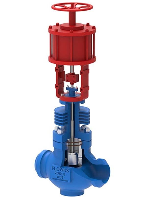
Labyrinth Multi-Stage Pressure Reduction Control Valve
About
Quick Specs Size:1" - 12" (DN25 - DN300) Pressure:Class 150 - 2500 Standard:IEC 60534, ASME B16.34, API 6D (pipeline configurations) Body Materials:A216 WCB, A351 CF8M, A182 F51, A182 F53
Trim Materials: Stellite 6, 316 SS, 17-4PH SS, Inconel 625 overlay
Design:Labyrinth multi-stage trim, up to 20+ pressure reduction stages, anti-cavitation, anti-flashing, low-noise
High Pressure Drop. High Velocity. High Damage——Unless You Break the Drop into Steps.
When a control valve takes a pressure drop from 1000 psi down to 50 psi in a single step, the media velocity through the vena contracta (the narrowest point in the flow passage) reaches extreme levels——hundreds of feet per second in some configurations. That velocity creates three destruction mechanisms simultaneously: cavitation bubbles form when local pressure drops below the vapor pressure, then collapse with explosive force against the trim surfaces; flashing occurs when the downstream pressure stays below vapor pressure and the media partially vaporizes through the valve, creating a high-velocity two-phase flow that erodes metal like sandblasting; and the turbulent velocity itself causes vibration, noise levels exceeding 100 dB, and mechanical fatigue in the trim and body. Single-stage trim handles moderate pressure drops——maybe 100-200 psi differential before cavitation damage starts accumulating. Above that, the valve gets rebuilt every few months, or it fails catastrophically when erosion opens a hole through the cage wall.
The labyrinth multi-stage trim breaks the total pressure drop into a series of small incremental steps——each step reduces pressure by a controlled fraction, and the cumulative series brings the media from inlet pressure to outlet pressure without any single step exceeding the cavitation threshold. Instead of 1000 psi dropping to 50 psi in one violent transition, the labyrinth path might take 20 stages: 1000→950→900→850→...→50. Each stage's pressure drop stays below the cavitation initiation threshold, local velocity stays within manageable limits, and the media reaches outlet pressure having passed through a controlled, gradual decompression path rather than a single violent expansion. No cavitation bubbles. No flashing-induced erosion. No destructive vibration. Noise levels drop by 20-40 dB compared to single-stage trim at the same total pressure drop. Trim service life extends from months to years——sometimes decades——because the flow conditions that destroy single-stage trim simply don't exist in the labyrinth flow path.
How the Labyrinth Path Works——Turns, Expansions, and Controlled Deceleration
The labyrinth trim is a stacked disc assembly——multiple precision-machined discs with intricate flow channels stacked together to form the complete pressure reduction path. Each disc contains a set of flow passages that route the media through a series of turns, expansions, and controlled-direction changes. The turns force the media to change direction——decelerating velocity and converting kinetic energy back into pressure through turbulence dissipation. The expansions increase the flow passage cross-section——allowing the media to spread out and slow down before the next set of turns compresses it again. The cumulative effect: each disc reduces pressure by a specific increment, and the disc stack reduces the total pressure from inlet to outlet through the combined series of increments. The number of discs (and therefore the number of stages) is determined by the total pressure drop the valve needs to handle——higher total drop requires more stages to keep each individual step within safe limits. FLOWKS labyrinth trim configurations range from a few stages for moderate pressure drops up to 20+ stages for extreme pressure reduction from Class 2500 down to low-pressure distribution service.
The disc geometry isn't random——it's engineered for the specific pressure drop profile the application requires. The flow channel shape, turn angle, expansion ratio, and passage cross-section on each disc are calculated to deliver the target pressure reduction per stage while maintaining velocity within the design envelope. Different total pressure drops require different disc geometries——a 500 psi total drop uses a different disc stack than a 2000 psi total drop, because the per-stage reduction increment and the velocity management at each stage differ. That's why labyrinth trim is application-specific: the disc stack is engineered for the actual inlet-to-outlet pressure profile, not assembled from a standard stage count hoping the stages happen to match the process conditions.
Where Labyrinth Valves Get Specified——The High-Drop Applications Boiler feedwater regulation——incoming water at high pump discharge pressure needs to be reduced to boiler operating pressure, with pressure drops often exceeding 500-1000 psi. Steam pressure...
Technical Specifications
| Size Range | 2”-24” |
| Pressure Class | Class300-2500 |
| Design Standard | ISA 75, IEC 60534 |
| Body Materials | WCB, WC6, WC9, CF8M, duplex steel, Monel and titanium |
| Parent Standards | ISA 75, IEC 60534 |
| Parent Size Range | 1" - 24" |
| Parent Pressure Class | Class 150 - 1500 |
Product Downloads
| Size Range | 2”-24” |
| Pressure Class | Class300-2500 |
| Design Standard | ISA 75, IEC 60534 |
| Body Materials | WCB, WC6, WC9, CF8M, duplex steel, Monel and titanium |
Need a quote?
Contact our engineering team for pricing and technical support on Labyrinth Multi-Stage Pressure Reduction Control Valve.
Request a QuoteLooking for more options?
Explore our complete range of industrial valves or contact us for custom solutions.
Ball Valves
FLOWKS offers floating ball valve, trunnion mounted ball valve and top entry ball valve for oil & gas, petrochemical and power generation. Designed per API 6D, API 608 and ASME B16.34.
DBB Valves
FLOWKS Double Block & Bleed (DBB) valves provide dual isolation with bleed verification in a single compact body. Replacing traditional multi-valve installations, FLOWKS DBB valves reduce weight, space and potential leak paths. Available in bolted bonnet, all-welded and expanding gate designs per API 6D and API 607.
Gate Valves
FLOWKS gate valves for isolation service in piping systems. Flexible wedge, solid wedge, slab and expanding gate designs per API 600, API 602 and ASME B16.34.
Globe Valves
FLOWKS globe valves for throttling and isolation. Standard, angle, Y-pattern and bellows seal configurations per API 602 and BS 1868.