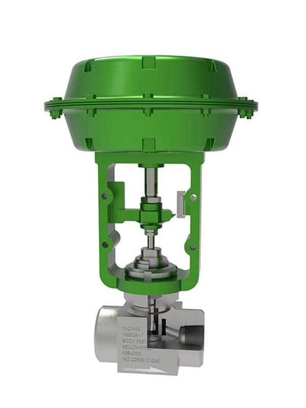
Low Flow Regulating Valve
About
Quick Specs Size: 1/2" - 1" (DN15 - DN25) Pressure: Class 150 - 600 Standard: IEC 60534, ASME B16.34 Body Materials: A216 WCB, A351 CF8M, A182 F316 Trim Materials: 316 SS, 17-4PH SS, Stellite 6 hard-facing, V-port micro-trim
Design: Linear stroke, micro-plug trim, pneumatic/electric actuated, precision Cv down to 0.001 When Cv 0.5 Is Too Much——You Need a Valve That Handles the Decimal Places
Standard control valves handle Cv values from single digits up to hundreds——that's the flow range most process applications occupy. But some applications need flow rates measured in drops, not gallons. Sample line injection. Reagent dosing into a reaction vessel. Catalyst addition at precisely controlled rates. Laboratory and pilot-plant scale process loops. Hydraulic system bleed-off at minimal rates. These applications don't need a valve that can pass 50 gallons per minute——they need one that passes 0.01 gallons per minute repeatably, and holds that rate steady when the control loop demands it. A standard Cv 5 valve throttled down to Cv 0.05 isn't controlling flow——it's choking it through a tiny gap near the closed position where flow characteristic accuracy collapses, seat leakage tolerance dominates, and the valve spends 95% of its travel range doing nothing useful.
FLOWKS low flow regulating valves are engineered for exactly this territory——travel ranges where the valve actually uses most of its stroke to modulate flow within the required range, not where it sits near closed and fights to maintain a trickle. The trim geometry is designed around small Cv values from the start: micro-plug profiles, restricted cage window configurations, and V-port micro-trim options that deliver equal-percentage or linear characteristics scaled to the actual flow range the process requires. The valve's rated Cv matches the application's maximum flow——not the next size up's minimum flow. That sizing discipline is what makes low flow regulation work. The valve has enough travel range to modulate precisely at the required flow levels, and the trim geometry is designed for those levels specifically.
Micro-Plug Trim——The Geometry That Makes Small Flow Work
A standard control valve plug has a profile designed for Cv values in the 1-100 range——the plug taper, the cage window geometry, and the flow passage dimensions are sized for flow rates that fill a normal pipe bore. A micro-plug trim has a profile designed for Cv 0.001 to 0.5——the plug is smaller, the cage windows are narrower, and the flow passage is restricted to match the actual flow area the application needs at full open. That geometry difference isn't just scaling down a standard plug——the flow characteristic curve, the plug-to-cage clearance at low travel positions, and the seat sealing geometry all have to be designed for the specific flow range. A standard plug throttled near closed loses characteristic accuracy because the plug profile isn't shaped for precise modulation at 2-5% of rated Cv. A micro-plug designed for that Cv range maintains characteristic accuracy because its profile is shaped for modulation at 20-80% of its rated travel——the same proportional range a standard valve uses at full-scale flow, but shifted down to the actual flow numbers the process needs.
V-port micro-trim takes the micro-plug concept and applies a V-shaped notch to the plug profile——giving equal-percentage characteristic behavior at micro-flow levels. The V-notch opening follows the same area-progression logic as V-port ball valves (small incremental area change at low travel, larger increments at high travel), but scaled to the restricted flow passage dimensions of the micro-trim. This gives the low flow valve the same control loop tuning advantage that V-port designs give to larger flow applications——stable control at minimum flow, responsive control at maximum, predictable characteristic behavior across the full travel range.
Seat Sealing at Low Flow——Where Leakage Tolerance Becomes the Real Problem
At normal flow rates, a control valve's seat leakage class (Class II, III, IV, V, VI per IEC 60534) is a secondary specification——the process can tolerate a few percent of rated Cv leaking past the closed seat because the process flow itself is orders of magnitude larger than the leakage rate. At micro-flow levels, seat leakage becomes the dominant concern. If the valve's rated Cv is 0.05 and the seat leakage at closed position is Class IV (0.01% of rated Cv), the leakage rate is 0.000005 Cv——trivial relative to the rated flow. But if the leakage is Class II (0.5% of rated Cv), the leakage rate is 0.00025 Cv——which is 5% of the rated flow. At low flow levels, the leakage rate isn't a small fraction of the process flow anymore——it's a significant percentage of it. That's why low flow regulating valves require tighter seat leakage classes than standard valves for the same...
Technical Specifications
| Size Range | 1/2”-2” |
| Pressure Class | Class150-2500 |
| Design Standard | ISA 75, IEC 60534 |
| Body Materials | A105, F11, F22, F304, F316, F304L, F316L, Aluminum Bronze, Stellite Alloy, Inconel 718, PTFE, RPTFE, PEEK, Flexible Graphite |
| Parent Standards | ISA 75, IEC 60534 |
| Parent Size Range | 1" - 24" |
| Parent Pressure Class | Class 150 - 1500 |
Product Downloads
| Size Range | 1/2”-2” |
| Pressure Class | Class150-2500 |
| Design Standard | ISA 75, IEC 60534 |
| Body Materials | A105, F11, F22, F304, F316, F304L, F316L, Aluminum Bronze, Stellite Alloy, Inconel 718, PTFE, RPTFE, PEEK, Flexible Graphite |
Need a quote?
Contact our engineering team for pricing and technical support on Low Flow Regulating Valve.
Request a QuoteLooking for more options?
Explore our complete range of industrial valves or contact us for custom solutions.
Ball Valves
FLOWKS offers floating ball valve, trunnion mounted ball valve and top entry ball valve for oil & gas, petrochemical and power generation. Designed per API 6D, API 608 and ASME B16.34.
DBB Valves
FLOWKS Double Block & Bleed (DBB) valves provide dual isolation with bleed verification in a single compact body. Replacing traditional multi-valve installations, FLOWKS DBB valves reduce weight, space and potential leak paths. Available in bolted bonnet, all-welded and expanding gate designs per API 6D and API 607.
Gate Valves
FLOWKS gate valves for isolation service in piping systems. Flexible wedge, solid wedge, slab and expanding gate designs per API 600, API 602 and ASME B16.34.
Globe Valves
FLOWKS globe valves for throttling and isolation. Standard, angle, Y-pattern and bellows seal configurations per API 602 and BS 1868.