🎛️

控制阀

4.6 / 5 (53 reviews)
ISA 75IEC 60534
Size Range
1" - 24"
Pressure Class
Class 150 - 1500
Standards
ISA 75, IEC 60534
Materials
Carbon Steel (A216 WCB), Stainless Steel (A351 CF8M)

Product Range

Select a series for detailed specifications, downloads and technical data.

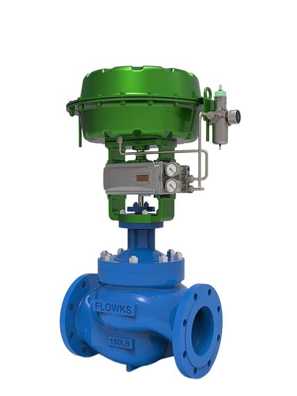
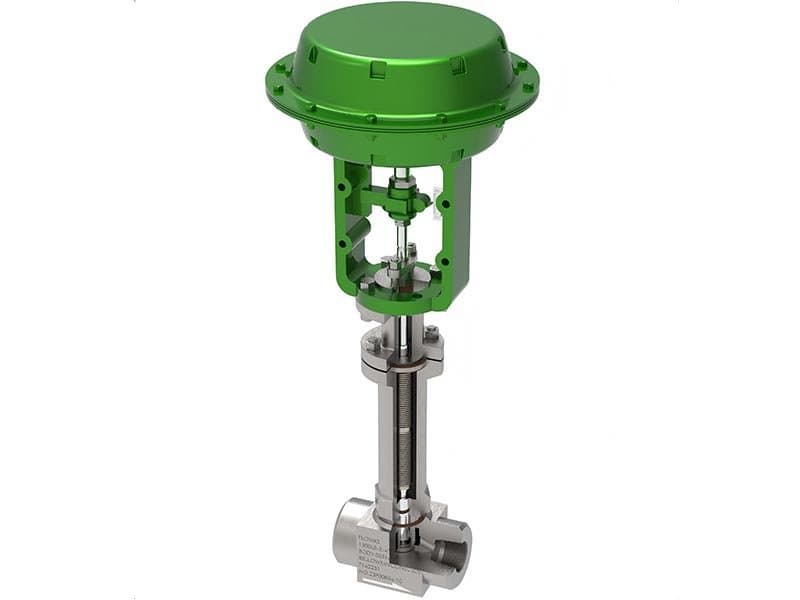
高性能线性行程控制阀

高性能线性行程控制阀

Quick Specs Size: 1/2" - 12" (DN15 - DN300) Pressure: Class 150 - 600 Standard: IEC 60534, API 608, ASME B16.34 Body Materials: A216 WCB, A351 CF8M, A182 F316, A182 F51 Seat/Trim Materials: PTFE, PEEK, Stellite 6, 316 SS, 17-4PH SS Design: Linear stroke, plug-type trim, pneumatic/electric actuated, equal-percentage or linear flow characteristic What This Valve Is——and Why It’s the One Most Projects End Up Specifying A linear stroke control valve moves the plug straight up and down——a vertical stroke along the valve stem axis, rather than rotating a ball or disc through a quarter-turn arc. That linear motion gives you something rotary valves struggle with: precise, repeatable flow modulation across the full travel range, with a flow characteristic curve you can actually depend on for process loop tuning. This is the workhorse control valve——the one that shows up on the majority of process control specifications across oil & gas, petrochemical, chemical, and power generation applications. Comparable in design philosophy to the Japanese CV3000 series, the FLOWKS high performance linear stroke control valve covers the same functional territory: robust body construction, multiple trim options for different pressure drops and media conditions, and flow characteristics engineered to match what the control system needs rather than forcing the system to compensate for what the valve delivers. The Plug and Cage——Where the Real Work Happens The trim assembly is what separates a functional control valve from a body with a hole in it. Inside the cage, the plug moves vertically through its travel range, and the gap between the plug profile and the cage windows defines the flow area at each position. FLOWKS offers two primary flow characteristics: equal-percentage and linear. Equal-percentage is the default choice for most process applications——small flow changes at low travel positions (stable control near minimum flow), progressively larger increments at higher positions (responsive control near maximum throughput). Linear characteristic delivers constant flow increment per unit of travel——straightforward, predictable, used where the process loop needs a direct proportional relationship between valve position and flow rate. The characteristic selection isn’t a guess——it’s determined by the process dynamics, the controller tuning requirements, and the installed gain curve the instrument engineer needs to achieve stable loop performance. Both plug profiles are available across the full size range; you specify what the control loop requires, not what happens to be in stock. Trim Material Options——Match the Material to What the Process Will Do to It Trim material selection determines whether your valve runs reliably for five years or gets rebuilt after two seasons. Standard trim configurations include 316 stainless steel for general process service, 17-4PH precipitation-hardening stainless for higher mechanical strength and moderate corrosion resistance, and Stellite 6 hard-facing overlay on the plug and cage seating surfaces for applications where erosion, cavitation damage, or high-velocity impingement would wear through standard stainless in months. The Stellite overlay isn’t a thin cosmetic coating——it’s a functional wear layer applied to the critical sealing and flow-path surfaces, extending trim service life under conditions that destroy softer materials. For elevated temperature applications, FLOWKS provides extended bonnet designs that move the packing area away from the body heat zone, keeping the stem packing within its operating temperature range even when the process media runs at several hundred degrees. Body Materials and Pressure Ratings A216 WCB carbon steel covers the majority of general-purpose applications——hydrocarbon lines, water service, steam distribution at moderate pressures and temperatures where carbon steel’s mechanical properties and corrosion resistance are adequate for the intended service duration. A351 CF8M stainless steps in for corrosive media containing chlorides, acids, and process chemicals that would attack carbon steel. A182 F316 handles higher-corrosion-resistance requirements where CF8M’s performance ceiling gets challenged. A182 F51 duplex provides both corrosion resistance and higher mechanical strength——used where the process demands both, typically in offshore and coastal installations where salt exposure adds an external corrosion dimension to the internal media challenge. Pressure ratings span Class 150 through Class 600——covering the range where linear stroke control valves deliver their best combination of flow control precision, sealing reliability, and cost efficiency. Pneumatic or Electric——The Actuator Choice Depends on How Your Plant Runs FLOWKS linear stroke control valves accept both pneumatic and electric actuator mounting. Pneumatic actuators (diaphragm or piston) remain the dominant choice in process plants——fast response, simple fail-safe positioning (spring-return closes or opens on air failure), and straightforward integration with existing instrument air systems. Electric actuators serve applications where instrument air isn’t available, where precise positioning accuracy matters more than response speed, or where the plant’s control architecture runs on electric signals without converting to pneumatic through I/P transducers. The actuator selection is specified with the valve——the stem connection, mounting dimensions, and thrust requirements are matched to the actuator’s output capability at the specified supply pressure or voltage. You don’t size the actuator separately and hope it fits; the engineering package covers the valve-actuator assembly as an integrated unit. Standards and Testing——Not Just Labels on a Datasheet IEC 60534 defines the control valve performance framework——flow characteristic classification, rangeability, rated Cv values, and predictable behavior within the control loop. This is the standard that process engineers use to specify control valves, and FLOWKS linear stroke valves are designed to meet its characteristic requirements. API 608 covers ball valve construction baseline where applicable to the body design. ASME B16.34 governs the pressure-temperature ratings——the envelope the valve is rated to operate within, and the boundary you don’t exceed without accepting the consequences. Every valve ships with pressure-tested shell integrity, seat sealing verification at high and low differential pressure, and travel-calibrated flow characteristic confirmation. The valve does what the datasheet says it does——verified before it leaves the factory, not promised and left for the field team to discover. FAQ What’s the difference between linear stroke and rotary control valves? Linear stroke moves the plug vertically——straight up and down. Rotary valves turn a ball or disc through a quarter-turn. Linear gives you more precise flow modulation across the full travel range, especially at low positions where rotary designs lose control resolution. That’s why linear stroke remains the dominant choice for continuous process throttling. Equal-percentage or linear characteristic——which one do I need? Equal-percentage is the default for most process applications. It gives stable control at low flow and responsive control at high flow——matching how most process loops actually behave. Linear is used where you need direct proportional response——constant flow change per unit of travel. Your instrument engineer decides based on the process dynamics, not based on what’s convenient. What does Stellite 6 trim actually do? Stellite 6 is a cobalt-based hard-facing alloy applied to the plug and cage seating surfaces. It resists erosion, cavitation damage, and high-velocity impingement far better than standard stainless steel. If your …(truncated)…

1/2" - 24"Class150~2500
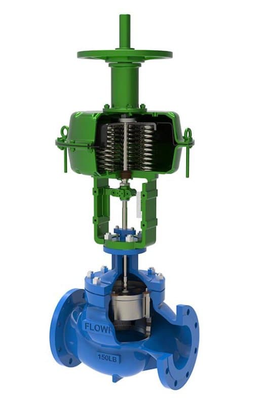
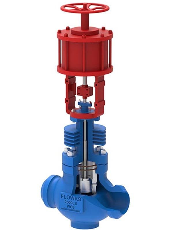
高性能线性行程控制阀,带手轮

高性能线性行程控制阀,带手轮

Quick Specs Size: 1/2" - 12" (DN15 - DN300) Pressure: Class 150 - 600 Standard: IEC 60534, API 608, ASME B16.34 Body Materials: A216 WCB, A351 CF8M, A182 F316, A182 F51 Seat/Trim Materials: PTFE, PEEK, Stellite 6, 316 SS, 17-4PH SS Design: Linear stroke, plug-type trim, pneumatic/electric actuated with integrated handwheel, equal-percentage or linear flow characteristic Same Valve, One Critical Addition Everything about this valve——the plug and cage trim, the flow characteristics, the body materials, the pressure ratings——is identical to the standard FLOWKS high performance linear stroke control valve. What's different is the handwheel mounted on the actuator assembly. That handwheel gives you manual control over the valve position when the actuator can't do the job——air supply failure, power outage, actuator maintenance, or commissioning and startup sequences where you need to set the valve to a specific position by hand before the control system takes over. On a process line running critical flow, losing valve control means losing process control. The handwheel isn't a backup for lazy days——it's emergency access to the valve stem when the automated system can't reach it. When the Handwheel Gets Used——and It's Not Just During Emergencies Plant startup is where the handwheel earns its value first. Before the control system is live, before the instrument air lines are pressurized, before the DCS has its loop configurations loaded——the valve needs to be positioned manually to establish initial flow conditions. An operator walks up, turns the handwheel, sets the valve to the startup position the process engineer specified, and holds it there until the automated system is ready to take command. Without the handwheel, you'd need to pressurize the air system first, stroke the valve through the actuator, and verify position through the control room——a longer sequence that delays startup and adds coordination complexity. Commissioning and loop tuning is the second scenario. When the instrument team is calibrating the control loop, they need to verify valve response at specific travel positions——10%, 25%, 50%, 75%, full open. Walking the valve through those positions manually with the handwheel is faster and more intuitive than commanding each step through the DCS, especially when the loop isn't yet configured and the actuator is responding to ad-hoc signals rather than a tuned control algorithm. The handwheel lets the commissioning team feel the valve's mechanical response directly——you can sense stiffness, detect plug-seat contact, verify that the stem moves freely through the full travel range without binding or hesitation. That hands-on verification is something remote actuator control can't provide. Actuator maintenance is the third. When the pneumatic actuator needs diaphragm replacement, or the electric actuator requires motor service, the valve has to stay in a safe position while the actuator is offline. The handwheel locks the valve at the position the process requires——closed for isolation safety, or partially open to maintain minimum flow while the actuator gets serviced. Without that manual hold, you'd need to either bypass the valve with a manual alternative in the piping, or shut down the process section entirely. The handwheel keeps the valve functional during actuator downtime. How the Handwheel Interacts with the Actuator The handwheel doesn't override the actuator——it supplements it. On pneumatic spring-return actuators, the handwheel connects to the stem through a clutch or manual override mechanism that engages when the handwheel is turned and disengages when the actuator resumes operation. You turn the handwheel——the stem moves. The actuator receives air——the handwheel clutch disengages, and the actuator takes over. There's no conflict between manual and automated operation; the mechanism transitions between them without requiring the operator to manually switch modes. On electric actuators, the handwheel typically engages through a declutch mechanism——pull the lever, turn the handwheel, push the lever back to return to motor operation. The transition sequence is simple enough that an operator can execute it in seconds during an emergency. FLOWKS handwheel assemblies are sized to match the actuator's thrust capability. The handwheel diameter, stem connection thread, and override torque rating are calculated to allow a single operator to move the valve through its full travel range against maximum differential pressure——not just at zero-pressure conditions. If you need to close the valve against full line pressure by hand, the handwheel has to deliver enough mechanical advantage to do it. That sizing isn't optional; it's part of the engineering package. Everything Else——Identical to the Standard Configuration Plug and cage trim options: 316 SS, 17-4PH, Stellite 6 hard-facing——same selection, same application logic. Flow characteristics: equal-percentage and linear——same profiles, same tuning rationale. Body materials: WCB, CF8M, F316, F51——same alloys, same process-matching approach. Pressure ratings: Class 150 through Class 600——same envelope. Pneumatic or electric actuation——same mounting options, same fail-safe configurations. The handwheel is an add-on to a proven platform, not a redesign of the valve itself. Standards and Testing——Plus Handwheel Override Verification IEC 60534, API 608, ASME B16.34——same compliance regime as the standard valve. The additional verification for the handwheel version covers override functionality: the handwheel engagement and disengagement sequence is tested across the full travel range under maximum rated differential pressure. The override mechanism has to work——not just at zero load in the factory, but against the actual process pressure the valve will face in service. That functional verification is part of the standard production test sequence for handwheel-configured valves. FAQ When would I specify a handwheel instead of the standard valve? Any application where losing automated control creates a process safety risk or a production interruption that costs more than the handwheel option. Critical flow lines, startup-intensive processes, plants with unreliable instrument air supply, and installations where commissioning and loop tuning require manual valve positioning——these are the standard handwheel specification triggers. Does the handwheel interfere with normal actuator operation? No. The handwheel engages through a clutch or declutch mechanism that disengages when the actuator resumes operation. You turn the handwheel manually——the stem responds. The actuator receives its control signal——the handwheel mechanism releases, and automated control takes over. No manual mode switching required by the operator. Can I close the valve by hand against full line pressure? Yes——if the handwheel is correctly sized. FLOWKS handwheel assemblies are engineered to allow a single operator to stroke the valve through its full travel range against maximum rated differential pressure. The handwheel diameter and stem thread pitch are calculated to deliver sufficient mechanical advantage. This sizing is part of the engineering package, not an afterthought. What happens to the handwheel position during normal automated operation? The handwheel stays in its last manually-set position or returns to a neutral position depending on the override mechanism design. It doesn't drift, doesn't interfere with actuator movement, and doesn't require the operator to reset it before returning to automated control. The transition between manual and automated modes is seamless by design. Is the handwheel version more expensive to maintain? Marginally——the override mechanism adds one more assembly to inspect during scheduled maintenance. The clutch or declutch linkage, the handwheel stem connection, and the engagement mechanism all get checked during turnaround inspections. The additional maintenance scope is minimal compared to the operational value the handwheel provides during emergencies and startup sequences.

1/2" - 24"Class150~2500
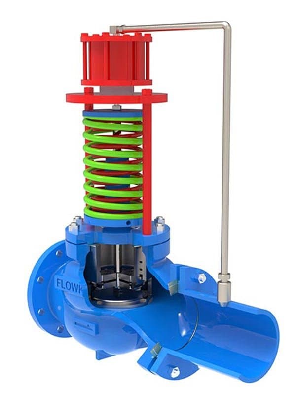
自驱动压力调节阀

自驱动压力调节阀

Quick Specs Size: 1/2" - 8" (DN15 - DN200) Pressure: Class 150 - 600 Standard: IEC 60534, ASME B16.34 Body Materials: A216 WCB, A351 CF8M, A182 F316 Seat/Trim Materials: PTFE, PEEK, Stellite 6, 316 SS Design: Self-actuated, no external power source, valve-before-pressure (reducing) and valve-after-pressure (backpressure) configurations No Air Supply. No Electricity. No External Power Source at All. A self-actuated pressure regulating valve doesn't need instrument air, doesn't need a DCS signal, doesn't need an electric actuator——it regulates pressure using the process media's own energy. The valve senses downstream (or upstream) pressure through an internal sensing port, compares that pressure against a pre-loaded spring force, and adjusts the plug position to maintain the set pressure automatically. Higher downstream pressure than the setpoint——the plug moves toward closed, reducing flow and letting pressure drop back toward target. Lower downstream pressure——the spring pushes the plug toward open, allowing more flow and letting pressure climb back. That feedback loop runs continuously, mechanically, without any external intervention. On remote well sites where instrument air doesn't exist, on pipeline branch stations miles from the nearest control room, on utility distribution networks where the cost of installing and maintaining an automated control system per valve exceeds the cost of the valve itself——self-actuated regulation is the practical answer. Two Configurations——Reducing Pressure or Maintaining Backpressure FLOWKS self-actuated pressure regulating valves come in two functional configurations determined by the sensing direction. Valve-after-pressure (commonly called pressure reducing) senses downstream pressure and throttles the valve to maintain a target outlet pressure below the inlet. This is the configuration you use when a high-pressure supply line feeds a lower-pressure distribution system——steam mains feeding low-pressure heating circuits, gas transmission lines feeding distribution networks, hydraulic supply lines feeding lower-pressure actuators. The valve automatically reduces whatever inlet pressure it receives down to the setpoint you've dialed into the spring preload. Valve-before-pressure (commonly called backpressure regulating) senses upstream pressure and throttles the valve to maintain a target inlet pressure above the outlet. This is the configuration you use when you need to hold pressure upstream of the valve——preventing a downstream pressure drop from pulling the upstream system below its minimum operating pressure, maintaining positive pressure on a tank blanketing system, or holding backpressure on a heat exchanger circuit to prevent flashing. The valve closes when upstream pressure drops below setpoint (restricting flow to hold pressure up), and opens when upstream pressure rises above setpoint (relieving excess pressure downstream). The mechanical logic is the same in both configurations——the spring preload defines the setpoint, the sensing port provides the feedback signal, and the plug position responds to the pressure difference between sensed pressure and spring force. What changes is which side of the valve the sensing port reads. How the Spring Sets the Pressure——and How You Adjust It The setpoint is defined by the spring preload——the force the spring exerts against the plug when the sensed pressure is exactly at the target value. Adjusting the setpoint means adjusting the spring compression, which is done through an external adjustment screw or nut on the spring housing. Turn the adjuster clockwise——more spring compression——higher setpoint. Turn counterclockwise——less compression——lower setpoint. The adjustment is continuous within the spring's range, not stepwise——you can set the valve to any pressure value within the rated range, not just to a few preset options. Spring selection matters because each spring covers a specific pressure range. A light spring handles low-pressure setpoints (a few psi to moderate ranges). A heavy spring handles high-pressure setpoints. The spring that ships with the valve is selected based on the setpoint the customer specifies——you don't get a generic spring and hope it covers your operating pressure. If the process requirements change and the setpoint needs to shift outside the original spring's range, the spring gets replaced——not the entire valve. Self-Actuated vs. Automated——When Each Makes Sense Self-actuated regulation trades precision for independence. The valve holds pressure within a band around the setpoint——not at an exact value. The regulation accuracy depends on the spring's linearity, the plug's flow characteristic, and the process flow conditions at the operating point. Typical self-actuated regulation accuracy falls in the ±1-5% range depending on configuration and process dynamics——adequate for distribution systems, utility networks, and remote installations where ±3% variation doesn't disrupt downstream operations. For applications that demand ±0.5% or tighter regulation, an automated control valve with a PID controller and continuous feedback from a pressure transmitter delivers superior accuracy——but it requires instrument air or electric power, a DCS or PLC connection, and the infrastructure to support continuous instrumented control. Self-actuated valves serve the applications where that infrastructure investment isn't justified by the precision requirement. If ±3% is good enough——and for most utility and distribution applications it is——self-actuated regulation delivers the required performance without the infrastructure cost. Body Materials and Trim——Same Logic, Different Application Focus A216 WCB carbon steel covers the majority of steam, water, and general utility pressure regulation——these are the media and pressure ranges where carbon steel performs reliably without corrosion concerns. A351 CF8M handles corrosive process streams——chemical distribution, sour gas, chloride-containing cooling water. A182 F316 steps in where CF8M's limits are challenged. The material logic follows the same process-matching approach as across the entire FLOWKS control valve series——match the body to what the media demands over the intended service life. Trim materials follow the same hierarchy: PTFE and PEEK for soft-seat tightness in clean service, Stellite 6 hard-facing for high-pressure drops where standard trim would erode prematurely. FAQ What pressure range can a self-actuated valve regulate? Depends on the spring selection. Light springs cover low-pressure ranges (a few psi to moderate pressures). Heavy springs cover higher ranges. Each spring has a defined range——the spring is selected based on the customer's specified setpoint. The valve body and trim handle the full Class 150-600 pressure envelope regardless of which spring is installed. Can I change the setpoint in the field? Yes——turn the external adjustment screw on the spring housing. Clockwise increases the setpoint, counterclockwise decreases it. The adjustment is continuous within the current spring's range. If the new setpoint falls outside the current spring's range, you replace the spring——not the valve. How accurate is self-actuated pressure regulation? Typical accuracy: ±1-5% of setpoint, depending on spring linearity, flow conditions, and process dynamics. For applications requiring tighter regulation (±0.5% or better), an automated control valve with PID control and continuous transmitter feedback is the correct choice. Self-actuated regulation serves applications where moderate accuracy is adequate and automated infrastructure isn't available or cost-justified. Does a self-actuated valve require any maintenance different from a standard control valve? The spring assembly requires periodic verification——spring preload should be checked during scheduled turnarounds to confirm the setpoint hasn drifted from its original setting. Spring fatigue over years of sustained compression can cause gradual setpoint shift. The sensing port and feedback linkage should be inspected for blockage or corrosion. Otherwise, maintenance follows the same trim inspection and seat sealing verification schedule as any control valve. Can I use a self-actuated valve for both reducing and backpressure regulation? No——the two configurations use different sensing directions and different plug-to-spring force relationships. A reducing valve senses downstream pressure. A backpressure valve senses upstream pressure. The physical construction differs. You specify which configuration you need based on whether the valve needs to reduce inlet pressure to a target outlet value, or maintain upstream pressure above a target minimum.

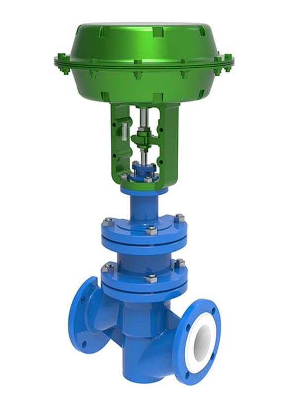
氟衬调节阀

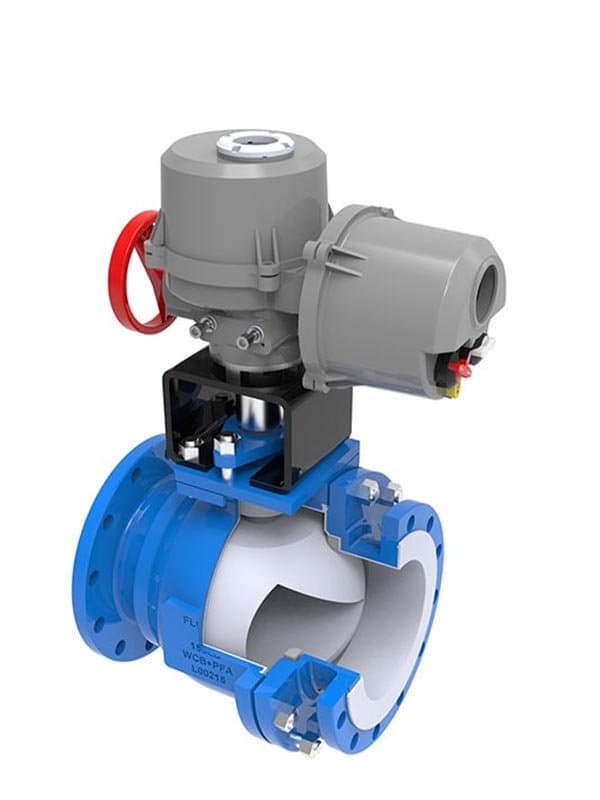
氟衬调节阀

Quick Specs Size: 1/2" - 8" (DN15 - DN200) Pressure: Class 150 - 300 Standard: IEC 60534, ASME B16.34 Body Materials:A216 WCB, A351 CF8M (external body——fluorine-lined internally)Lining Materials: PTFE, PFA, FEP Trim Materials: PTFE-lined plug, PFA-coated cage, 316 SS core structure with fluorine overlay Design: Linear stroke, plug-type trim, pneumatic/electric actuated, full fluorine-lined flow passage When Carbon Steel and Stainless Steel Both Fail——Fluorine Steps In Concentrated sulfuric acid at 98%. Hydrochloric acid at 30%. Chlorine gas. Hydrofluoric acid. Bromine. These are the media that destroy carbon steel in weeks, pit stainless steel in months, and challenge even high-nickel alloys over extended service. A fluorine-lined regulating valve puts a continuous barrier of PTFE, PFA, or FEP between the process media and the metal body——the fluoropolymer lining covers every surface the media touches: the body bore, the seat pocket, the plug surface, the cage windows, the stem shield. The metal body provides structural strength and pressure containment. The lining provides chemical resistance. You get both——rigid structural integrity from the steel shell, and near-universal corrosion resistance from the fluoropolymer barrier that the media can't penetrate, can't dissolve, and can't degrade under normal process temperatures. FLOWKS fluorine-lined regulating valves are designed for precisely this service category where the process chemistry is too aggressive for bare metal trim, but the flow regulation requirement demands control valve precision rather than simple on-off isolation. Most fluoropolymer valve offerings in the market are isolation valves——lined ball valves or lined butterfly valves that give you open or closed, not throttling control. A fluorine-lined regulating valve adds the plug and cage flow modulation capability to the corrosion-resistant lining system, giving you both chemical resistance and process control in a single valve assembly. The Lining System——Not Just a coating, It's a Full Flow Passage Barrier The fluoropolymer lining isn't applied as a thin spray coating——it's a molded lining that covers the complete internal flow passage as a continuous shell. PTFE is the baseline lining material—— chemically inert to virtually all industrial process fluids at temperatures up to its operational limit, with the lowest coefficient of friction in the lining material lineup (smooth internal surfaces that resist fouling and buildup from viscous or precipitating media). PFA offers higher temperature capability and better stress-crack resistance than PTFE——used where the process runs hotter than PTFE's comfort zone or where the lining sees repeated thermal cycling that could cause PTFE to develop micro-cracks over years of service. FEP provides excellent chemical resistance with easier processing characteristics than PTFE——used where the lining geometry requires tighter dimensional control during manufacturing. The lining thickness is engineered for the application, not standardized to a minimum nominal value. High-velocity media with erosive particles requires thicker lining to compensate for gradual surface wear. Low-velocity clean service can run thinner lining without sacrificing service life. The lining thickness decision follows the same logic as trim material selection across the FLOWKS control valve series——match the barrier to what the media will do to it over the intended service duration. Plug and Cage Trim——Fluorine-Coated, Not Bare Metal The plug and cage assembly in a fluorine-lined valve can't use bare metal seating surfaces——the media would attack the trim directly at the sealing contact point. FLOWKS uses PTFE-lined plug surfaces and PFA-coated cage windows to maintain the chemical barrier across the full flow modulation path. The underlying core structure (plug body, cage frame) is 316 stainless steel——providing mechanical rigidity and dimensional stability. The fluoropolymer overlay on the seating surfaces provides the chemical isolation that keeps the metal core from ever touching the process media. The combination gives you trim that throttles precisely (metal core maintains plug profile accuracy under load) and resists corrosion (fluoropolymer overlay keeps the media away from the metal). The trade-off: fluoropolymer seating surfaces are softer than metal hard seats. Soft seats deliver tighter shutoff in clean service——zero leakage class is achievable with PTFE seating under normal closing force. But under high-velocity flow, abrasive media, or frequent cycling between throttling and closed positions, the soft seating surfaces wear faster than Stellite or tungsten carbide hard-facing would. The valve design compensates where it can——lining thickness on the seating zones, optimized plug-to-cage contact geometry, and controlled closing force from the actuator to minimize seating surface deformation during repeated closed-position cycles. But the fundamental reality remains: fluoropolymer seats sacrifice some wear resistance in exchange for chemical resistance that hard metal seats can't provide. The application determines whether that trade-off is acceptable——and in concentrated acid service, it's not just acceptable, it's the only viable option. Pressure and Temperature Limits——Where Fluoropolymer Lines Draw the Boundary Class 150 through Class 300 covers the pressure range where fluoropolymer-lined valves deliver reliable long-term performance. The lining system can withstand higher pressures——but sustained loading at Class 600 and above compresses the lining material between the metal body and the process pressure, potentially causing lining deformation, seat creep, and dimensional shift in the flow passage geometry over time. Class 150-300 keeps the lining under comfortable stress levels where dimensional stability holds for the intended service duration. Temperature limits follow the fluoropolymer material's properties. PTFE: up to approximately 200°C (392°F) continuous service——higher temperatures cause PTFE to soften and lose mechanical strength at the seating surfaces. PFA: up to approximately 260°C (500°F)——better thermal stability, used where PTFE's temperature ceiling is too restrictive. FEP: up to approximately 200°C——similar to PTFE in temperature capability, chosen for its processing advantages rather than thermal performance. These temperature limits are real engineering boundaries——exceeding them doesn't just risk lining damage, it fundamentally changes the seating surface's mechanical properties and compromises both sealing and flow modulation accuracy. FAQ What media is a fluorine-lined regulating valve designed for? Concentrated acids (sulfuric, hydrochloric, nitric, hydrofluoric), chlorine gas, bromine, strong alkalis, and any process chemical that attacks both carbon steel and stainless steel. If the media corrodes bare metal trim at a rate that makes standard valve materials impractical, fluorine lining is the correct barrier approach. Can a fluorine-lined valve throttle as precisely as a standard metal-trim control valve? Yes——the metal core structure maintains plug profile accuracy, and the fluoropolymer overlay on seating surfaces doesn't significantly affect flow characteristic behavior. The flow modulation precision comes from the plug and cage geometry, which is defined by the metal core. The lining adds chemical resistance without compromising flow characteristic accuracy. What's the difference between PTFE, PFA, and FEP lining? PTFE: widest chemical resistance, lowest friction coefficient, temperature limit ~200°C. PFA: higher temperature capability (~260°C), better stress-crack resistance under thermal cycling. FEP: similar chemical resistance to PTFE with easier manufacturing processing——used where tight lining dimensional control is needed. The choice depends on process temperature and lining geometry requirements. Why Class 150-300 instead of Class 600? Sustained high pressure compresses the fluoropolymer lining between the metal body shell and the process pressure, causing lining creep and dimensional shift over time. Class 150-300 keeps lining stress within the range where dimensional stability holds for the intended service life. For higher pressure applications, different valve constructions (metal-seated with alloy trim) become more appropriate. Does the lining wear out over time? Yes——fluoropolymer lining gradually erodes under high-velocity flow, abrasive media, and repeated seating cycle contact. The lining thickness is engineered to provide sufficient service life for the specified conditions. When the lining reaches its wear limit, the trim assembly gets relined or replaced——the metal body shell remains intact and reusable.

1/2" - 24"Class150 300
低流量调节阀

低流量调节阀

Quick Specs Size: 1/2" - 1" (DN15 - DN25) Pressure: Class 150 - 600 Standard: IEC 60534, ASME B16.34 Body Materials: A216 WCB, A351 CF8M, A182 F316 Trim Materials: 316 SS, 17-4PH SS, Stellite 6 hard-facing, V-port micro-trim Design: Linear stroke, micro-plug trim, pneumatic/electric actuated, precision Cv down to 0.001 When Cv 0.5 Is Too Much——You Need a Valve That Handles the Decimal Places Standard control valves handle Cv values from single digits up to hundreds——that's the flow range most process applications occupy. But some applications need flow rates measured in drops, not gallons. Sample line injection. Reagent dosing into a reaction vessel. Catalyst addition at precisely controlled rates. Laboratory and pilot-plant scale process loops. Hydraulic system bleed-off at minimal rates. These applications don't need a valve that can pass 50 gallons per minute——they need one that passes 0.01 gallons per minute repeatably, and holds that rate steady when the control loop demands it. A standard Cv 5 valve throttled down to Cv 0.05 isn't controlling flow——it's choking it through a tiny gap near the closed position where flow characteristic accuracy collapses, seat leakage tolerance dominates, and the valve spends 95% of its travel range doing nothing useful. FLOWKS low flow regulating valves are engineered for exactly this territory——travel ranges where the valve actually uses most of its stroke to modulate flow within the required range, not where it sits near closed and fights to maintain a trickle. The trim geometry is designed around small Cv values from the start: micro-plug profiles, restricted cage window configurations, and V-port micro-trim options that deliver equal-percentage or linear characteristics scaled to the actual flow range the process requires. The valve's rated Cv matches the application's maximum flow——not the next size up's minimum flow. That sizing discipline is what makes low flow regulation work. The valve has enough travel range to modulate precisely at the required flow levels, and the trim geometry is designed for those levels specifically. Micro-Plug Trim——The Geometry That Makes Small Flow Work A standard control valve plug has a profile designed for Cv values in the 1-100 range——the plug taper, the cage window geometry, and the flow passage dimensions are sized for flow rates that fill a normal pipe bore. A micro-plug trim has a profile designed for Cv 0.001 to 0.5——the plug is smaller, the cage windows are narrower, and the flow passage is restricted to match the actual flow area the application needs at full open. That geometry difference isn't just scaling down a standard plug——the flow characteristic curve, the plug-to-cage clearance at low travel positions, and the seat sealing geometry all have to be designed for the specific flow range. A standard plug throttled near closed loses characteristic accuracy because the plug profile isn't shaped for precise modulation at 2-5% of rated Cv. A micro-plug designed for that Cv range maintains characteristic accuracy because its profile is shaped for modulation at 20-80% of its rated travel——the same proportional range a standard valve uses at full-scale flow, but shifted down to the actual flow numbers the process needs. V-port micro-trim takes the micro-plug concept and applies a V-shaped notch to the plug profile——giving equal-percentage characteristic behavior at micro-flow levels. The V-notch opening follows the same area-progression logic as V-port ball valves (small incremental area change at low travel, larger increments at high travel), but scaled to the restricted flow passage dimensions of the micro-trim. This gives the low flow valve the same control loop tuning advantage that V-port designs give to larger flow applications——stable control at minimum flow, responsive control at maximum, predictable characteristic behavior across the full travel range. Seat Sealing at Low Flow——Where Leakage Tolerance Becomes the Real Problem At normal flow rates, a control valve's seat leakage class (Class II, III, IV, V, VI per IEC 60534) is a secondary specification——the process can tolerate a few percent of rated Cv leaking past the closed seat because the process flow itself is orders of magnitude larger than the leakage rate. At micro-flow levels, seat leakage becomes the dominant concern. If the valve's rated Cv is 0.05 and the seat leakage at closed position is Class IV (0.01% of rated Cv), the leakage rate is 0.000005 Cv——trivial relative to the rated flow. But if the leakage is Class II (0.5% of rated Cv), the leakage rate is 0.00025 Cv——which is 5% of the rated flow. At low flow levels, the leakage rate isn't a small fraction of the process flow anymore——it's a significant percentage of it. That's why low flow regulating valves require tighter seat leakage classes than standard valves for the same application. FLOWKS low flow trim assemblies deliver Class V or Class VI seat leakage as standard——not as an expensive upgrade option. The micro-plug geometry and seating surface design are optimized for tight closure at the restricted bore dimensions where standard trim can't achieve Class V reliably. Body Materials and Pressure——Small Size, Full Pressure Capability A216 WCB carbon steel for general service——steam, water, hydrocarbon sampling, chemical injection at moderate temperatures where carbon steel's corrosion resistance is adequate. A351 CF8M stainless for corrosive media——sample lines carrying acidic process streams, reagent dosing into corrosive reactor vessels. A182 F316 for higher corrosion resistance requirements. The body material logic is the same as across the entire FLOWKS series——match the body to what the media demands. The size is small, but the pressure capability isn't: Class 150 through Class 600——the same pressure envelope as the standard high performance linear stroke valve, applied here in a compact body designed for micro-flow trim. FAQ What's the smallest Cv this valve can deliver? Cv 0.001——using restricted micro-trim and V-port micro-plug geometry. Standard micro-trim covers Cv 0.01 to 0.5. The specific Cv value is determined by the plug profile and cage window configuration, which are selected based on the process flow range requirement. Can I use a standard control valve throttled near closed for low flow regulation? Not effectively. A standard Cv 5 valve operating at Cv 0.05 is using less than 1% of its travel range for flow modulation. At that position, the plug profile isn't shaped for precise control, the flow characteristic is unpredictable, and seat leakage relative to the process flow is significant. A low flow valve with matched micro-trim uses 20-80% of its travel range——the same proportional modulation range a standard valve uses at full-scale flow, but correctly sized for the actual flow requirement. What seat leakage class does the low flow trim achieve? Class V (fugitive emission grade) or Class VI (bubble-tight) as standard. At micro-flow levels, tighter seat leakage is necessary because leakage relative to rated flow becomes a significant percentage at lower Cv values. The micro-plug seating geometry is optimized for tight closure at the restricted bore dimensions. What applications typically specify low flow regulating valves?** Sample line injection and analysis loops, reagent and catalyst dosing into reaction vessels, laboratory and pilot-plant process control, hydraulic system bleed-off at minimal rates, chemical addition at precisely controlled微量 rates, and any application where the required flow range is below what standard trim can modulate effectively. Can the low flow valve handle high pressure drops? Yes——Class 150 through Class 600 pressure capability, same as the standard series. The body handles the full pressure envelope. For high pressure drops at low flow, Stellite 6 hard-facing on the micro-trim seating surfaces extends service life where the high-velocity micro-jet through the restricted trim would erode standard stainless trim prematurely.

1/2”-2”Class150-2500
迷宫式多级减压控制阀

迷宫式多级减压控制阀

Quick Specs Size:1" - 12" (DN25 - DN300) Pressure:Class 150 - 2500 Standard:IEC 60534, ASME B16.34, API 6D (pipeline configurations) Body Materials:A216 WCB, A351 CF8M, A182 F51, A182 F53 Trim Materials: Stellite 6, 316 SS, 17-4PH SS, Inconel 625 overlay Design:Labyrinth multi-stage trim, up to 20+ pressure reduction stages, anti-cavitation, anti-flashing, low-noise High Pressure Drop. High Velocity. High Damage——Unless You Break the Drop into Steps. When a control valve takes a pressure drop from 1000 psi down to 50 psi in a single step, the media velocity through the vena contracta (the narrowest point in the flow passage) reaches extreme levels——hundreds of feet per second in some configurations. That velocity creates three destruction mechanisms simultaneously: cavitation bubbles form when local pressure drops below the vapor pressure, then collapse with explosive force against the trim surfaces; flashing occurs when the downstream pressure stays below vapor pressure and the media partially vaporizes through the valve, creating a high-velocity two-phase flow that erodes metal like sandblasting; and the turbulent velocity itself causes vibration, noise levels exceeding 100 dB, and mechanical fatigue in the trim and body. Single-stage trim handles moderate pressure drops——maybe 100-200 psi differential before cavitation damage starts accumulating. Above that, the valve gets rebuilt every few months, or it fails catastrophically when erosion opens a hole through the cage wall. The labyrinth multi-stage trim breaks the total pressure drop into a series of small incremental steps——each step reduces pressure by a controlled fraction, and the cumulative series brings the media from inlet pressure to outlet pressure without any single step exceeding the cavitation threshold. Instead of 1000 psi dropping to 50 psi in one violent transition, the labyrinth path might take 20 stages: 1000→950→900→850→...→50. Each stage's pressure drop stays below the cavitation initiation threshold, local velocity stays within manageable limits, and the media reaches outlet pressure having passed through a controlled, gradual decompression path rather than a single violent expansion. No cavitation bubbles. No flashing-induced erosion. No destructive vibration. Noise levels drop by 20-40 dB compared to single-stage trim at the same total pressure drop. Trim service life extends from months to years——sometimes decades——because the flow conditions that destroy single-stage trim simply don't exist in the labyrinth flow path. How the Labyrinth Path Works——Turns, Expansions, and Controlled Deceleration The labyrinth trim is a stacked disc assembly——multiple precision-machined discs with intricate flow channels stacked together to form the complete pressure reduction path. Each disc contains a set of flow passages that route the media through a series of turns, expansions, and controlled-direction changes. The turns force the media to change direction——decelerating velocity and converting kinetic energy back into pressure through turbulence dissipation. The expansions increase the flow passage cross-section——allowing the media to spread out and slow down before the next set of turns compresses it again. The cumulative effect: each disc reduces pressure by a specific increment, and the disc stack reduces the total pressure from inlet to outlet through the combined series of increments. The number of discs (and therefore the number of stages) is determined by the total pressure drop the valve needs to handle——higher total drop requires more stages to keep each individual step within safe limits. FLOWKS labyrinth trim configurations range from a few stages for moderate pressure drops up to 20+ stages for extreme pressure reduction from Class 2500 down to low-pressure distribution service. The disc geometry isn't random——it's engineered for the specific pressure drop profile the application requires. The flow channel shape, turn angle, expansion ratio, and passage cross-section on each disc are calculated to deliver the target pressure reduction per stage while maintaining velocity within the design envelope. Different total pressure drops require different disc geometries——a 500 psi total drop uses a different disc stack than a 2000 psi total drop, because the per-stage reduction increment and the velocity management at each stage differ. That's why labyrinth trim is application-specific: the disc stack is engineered for the actual inlet-to-outlet pressure profile, not assembled from a standard stage count hoping the stages happen to match the process conditions. Where Labyrinth Valves Get Specified——The High-Drop Applications Boiler feedwater regulation——incoming water at high pump discharge pressure needs to be reduced to boiler operating pressure, with pressure drops often exceeding 500-1000 psi. Steam pressure reduction——high-pressure steam mains feeding low-pressure distribution systems, where single-stage trim would generate cavitation and noise levels that violate plant occupational health standards. Compressor discharge regulation——high-pressure gas from compressor stations feeding lower-pressure pipeline networks, where flashing and erosion would destroy standard trim in weeks. Petrochemical process letdown——reactor discharge at elevated pressure feeding downstream separation equipment at lower operating pressure, where the media chemistry combined with high velocity makes erosion rates unacceptable with conventional trim. These are the applications where specifying a standard control valve and hoping it survives is not an option——the process conditions dictate labyrinth multi-stage trim, and the question is how many stages and what disc geometry, not whether to use labyrinth or conventional. Noise Reduction——Not Just a Comfort Feature, a Regulatory Requirement In power plants and petrochemical facilities, control valve noise at high pressure drops routinely exceeds 100 dB——well above occupational health limits for sustained worker exposure, and often above regulatory noise emission standards for industrial facilities. Labyrinth trim doesn't just reduce trim damage——it reduces noise by 20-40 dB compared to single-stage trim at equivalent pressure drop. The staged pressure reduction eliminates the violent expansion at the vena contracta that generates most of the acoustic energy in single-stage valves. Each stage's controlled velocity change produces far less turbulent noise than a single-step expansion. The cumulative noise level at the valve outlet is the sum of many small, quiet pressure changes rather than one loud explosive expansion. In applications where noise regulation is enforced——and in most industrial jurisdictions it is——labyrinth trim is the compliance solution, not just a performance upgrade. FAQ What pressure drop range requires labyrinth multi-stage trim? Generally, any application with pressure drop exceeding 200-300 psi where the downstream pressure is above the media's vapor pressure (cavitation risk), or where downstream pressure is below vapor pressure (flashing risk). The specific stage count depends on the total pressure drop and the media's vapor pressure relative to the outlet pressure. FLOWKS engineering determines the stage count based on the actual process conditions——not from a generic rule of thumb. How many stages does a labyrinth trim typically have? From a few stages (3-5) for moderate pressure drops, up to 20+ stages for extreme pressure reduction (Class 2500 inlet to low-pressure outlet). The number is determined by the total pressure drop and the per-stage reduction increment needed to keep each stage below the cavitation threshold. In properly designed configurations where each stage's pressure drop stays below the cavitation threshold——yes, cavitation is eliminated. The media never experiences a pressure drop below its vapor pressure at any point in the labyrinth path. The total pressure reduction is achieved through cumulative small steps, each of which stays in the non-cavitating regime. What's the noise reduction compared to single-stage trim? 20-40 dB reduction at equivalent total pressure drop. The staged decompression path eliminates the violent vena contracta expansion that generates most acoustic energy in single-stage valves. Each stage produces a small, controlled velocity change with minimal turbulent noise generation. The cumulative noise level is the sum of many quiet pressure changes, not one loud expansion. Can labyrinth trim handle flashing service? Yes——labyrinth trim manages flashing by controlling the two-phase flow expansion across multiple stages rather than allowing the media to flash through a single violent expansion. The staged approach reduces the velocity of the flashing two-phase flow and distributes the erosive energy across the disc stack rather than concentrating it at a single point. Trim service life in flashing service with labyrinth design is significantly longer than with single-stage trim——months to years instead of weeks.

2”-24”Class300-2500
衬里耐磨V型球阀

衬里耐磨V型球阀

Quick Specs Size: 1" - 12" (DN25 - DN300) Pressure:Class 150 - 600 Standard:IEC 60534, API 608, ASME B16.34 Body Materials: A216 WCB, A351 CF8M, A182 F316 (with internal wear-resistant lining) Lining/Hard-facing Materials:Ceramic lining, TCC (tungsten carbide ceramic) spray coating, Stellite 6 overlay Trim Design: V-port ball with wear-resistant surface treatment, spring-loaded seats Design:Rotary V-ball, pneumatic/electric actuated, equal-percentage flow characteristic V-Ball for Flow Control——Hard-Faced for Media That Destroys Soft Trim V-ball control valve gives you equal-percentage flow characteristic, bidirectional sealing, and the shear-cutting action that handles fibrous and particulate media better than any linear plug design. But when the process media carries abrasive solids——mineral slurry, catalyst fines, coal wash tailings, phosphate sludge, ash-laden wastewater——the V-notch edge and the seat sealing surfaces get ground down by the media itself. Standard PTFE seats last weeks in slurry service. Standard stainless trim erodes to leakage within months. The V-ball geometry handles the flow control requirement, but the trim material can't survive what the process pumps through it. That's the gap this valve fills: V-ball flow regulation capability with wear-resistant lining and hard-facing systems that hold up under abrasive, erosive, and high-temperature conditions that destroy conventional soft-seat and standard metal trim. Three Wear-Resistant Options——Ceramic, TCC, and Stellite——Each for Different Destruction Modes FLOWKS lined wear-resistant V-ball control valves offer three distinct wear-resistant surface treatment systems, each targeting a specific destruction mechanism the process media imposes on the trim. Ceramic lining covers the internal flow passage surfaces——the body bore, the seat pocket, and the ball surface contact zones——with a hard, chemically inert ceramic layer. Ceramic is the hardest lining option in the lineup——significantly harder than any metal alloy or carbide coating. It resists abrasive particle impingement (solid particles hitting the surface at flow velocity) and erosion from high-velocity slurry flow better than any alternative. The trade-off: ceramic is brittle. Impact loading from large solid objects (oversized rocks, metal debris in the slurry) can chip or crack the ceramic lining at the impact point. Ceramic lining is the correct choice for fine-particle abrasive slurry service where the erosive mechanism is sustained particle impingement at flow velocity——not where the media carries large impact-loaded objects that would fracture the ceramic layer. TCC (tungsten carbide ceramic) spray coating applies a tungsten carbide-based ceramic composite coating to the ball surface, the seat sealing faces, and the high-velocity flow path zones through the V-notch area. TCC is not as hard as pure ceramic——but it's far harder than Stellite or any standard metal alloy, and it has better impact resistance than ceramic because the tungsten carbide matrix has some ductility that pure ceramic lacks. TCC handles both abrasive erosion and moderate impact loading——solid particles hitting at flow velocity, plus occasional larger objects that would chip pure ceramic. TCC also performs well at elevated temperatures——the tungsten carbide matrix maintains hardness and dimensional stability at temperatures where Stellite softens and where PTFE/PEEK seats would fail entirely. High-temperature abrasive service——hot ash slurry, high-temperature catalyst circulation, steam-containing erosive media——is TCC's primary application domain. Stellite 6 overlay is the established hard-facing option——cobalt-based alloy welded onto the ball seating surface and the seat contact faces. Stellite is less hard than TCC and ceramic, but it has the best impact resistance of the three options——it can absorb large-object impacts without cracking or chipping. Stellite also has proven long-term service history across thousands of installations in erosive process service——the material behavior, wear rate progression, and failure mode characteristics are well-documented and well-understood by maintenance teams who've been working with Stellite-trimmed valves for decades. For applications where the media carries larger abrasive particles or occasional solid objects (mineral processing, mining slurry, coarse ash handling), Stellite's impact toughness makes it the safer choice despite its lower hardness rating compared to TCC and ceramic. The V-Ball Geometry——Same Cutting Edge, Now Protected The V-port ball profile operates identically to the standard FLOWKS V-ball control valve——equal-percentage characteristic, bidirectional sealing from spring-loaded seats, and the V-notch edge that cuts through fibrous and stringy media on every close cycle. The wear-resistant surface treatment doesn't change the V-ball's flow characteristic behavior——the ball profile geometry is defined by the underlying metal substrate, and the lining or coating is applied over that geometry without altering the flow path shape. What changes is the surface that the media touches. Instead of bare stainless steel or PTFE, the media encounters ceramic, TCC, or Stellite at the critical contact points——the V-notch cutting edge, the seat sealing faces, and the high-velocity flow zones where erosive damage concentrates. The V-notch edge gets special attention in the wear-resistant configuration. On a standard V-ball, the V-edge cuts through fibrous material——but in abrasive slurry service, the V-edge itself gets worn down by the media, gradually losing its sharp profile and eventually becoming a rounded edge that can't shear effectively. The wear-resistant surface treatment on the V-edge maintains the cutting geometry under abrasive attack——ceramic and TCC are hard enough to resist edge rounding from fine-particle erosion, while Stellite's ductility lets the edge deform slightly under impact without cracking. The V-edge stays functional for years in slurry service where a standard stainless V-edge would round off in months. Spring-Loaded Seats——Bidirectional Sealing in Abrasive Service Spring-loaded seats press independently against the ball from upstream and downstream directions——the same bidirectional sealing principle as the standard V-ball series. In abrasive service, the seat sealing faces receive the same wear-resistant treatment as the ball surface——Stellite overlay, TCC coating, or ceramic lining depending on the specified configuration. The spring preload maintains seating contact force even as the sealing faces gradually wear——the springs compensate for surface wear by maintaining compression, extending the period where the valve achieves tight shutoff before the sealing faces need replacement. That spring compensation is particularly valuable in abrasive service where sealing face wear is continuous and predictable——the valve maintains acceptable leakage class throughout the designed wear interval, rather than losing shutoff capability abruptly when the seat surface reaches a wear threshold. FAQ Ceramic, TCC, or Stellite——which one do I specify? Ceramic for fine-particle abrasive slurry where the erosive mechanism is sustained impingement at flow velocity——no large solid objects in the media. TCC for abrasive service at elevated temperatures, and where the media carries particles that would chip pure ceramic——TCC has enough ductility to handle moderate impact. Stellite for coarse abrasive media with larger particles or occasional solid objects——Stellite's impact toughness absorbs impacts without cracking, and its decades of proven service history make it the conservative choice where failure mode predictability matters. Does the wear-resistant lining affect the V-ball's flow characteristic? No——the lining and coating are applied over the ball's underlying metal geometry without altering the V-notch profile shape or the flow passage dimensions. The equal-percentage characteristic behavior comes from the V-notch geometry, which is defined by the substrate. The surface treatment protects that geometry from abrasive wear without changing it. How long does the wear-resistant trim last compared to standard stainless? Service life depends on the specific media conditions——particle size, concentration, velocity, and chemical composition. In typical mineral slurry service, ceramic and TCC trim extends service life 5-10x compared to standard 316 SS trim. Stellite extends 3-5x. The exact multiplier varies by application——FLOWKS engineering provides estimated service intervals based on the customer's specific process conditions. Can the wear-resistant V-ball achieve tight shutoff? Yes——spring-loaded seats with hard-facing on the sealing faces achieve Class IV or Class V leakage depending on the hard-facing material and the seating geometry. Ceramic seats deliver Class V. TCC and Stellite seats typically achieve Class IV. Hard-faced seats don't achieve Class VI (bubble-tight)——that's soft-seat territory. But Class IV-V leakage is the practical standard for abrasive service where the priority is trim survival, not zero-leakage shutoff. What happens when the lining or coating eventually wears through? The trim assembly is replaced——ball, seats, and any lining components that have reached their wear limit. The body shell remains intact and reusable (the lining/coating protects the body's internal surfaces during trim service life; once the trim reaches wear limit, the body gets re-lined or the worn trim components are replaced with new ones). The maintenance cycle is planned based on the estimated service interval for the specified process conditions——you don't wait for failure, you replace on schedule.

2”-16”Class150-600
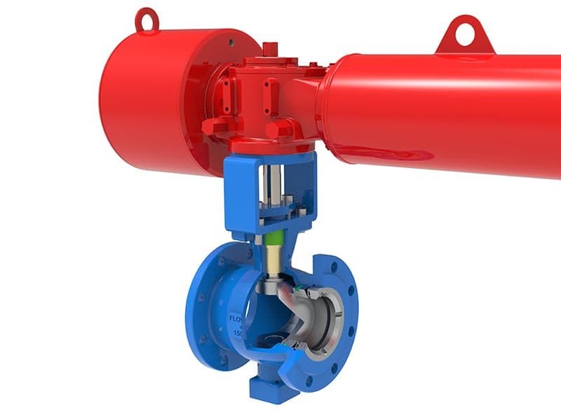
高性能V型球控制阀

高性能V型球控制阀

Quick Specs Size:1" - 12" (DN25 - DN300) Pressure: Class 150 - 600 Standard: IEC 60534, API 608, ASME B16.34 Body Materials: A216 WCB, A351 CF8M, A182 F316, A182 F51 Seat Materials: PTFE, PEEK, Stellite 6, metal hard seat Trim Design: V-port ball, spring-loaded bidirectional seats, equal-percentage flow characteristic Design:Rotary V-ball, pneumatic/electric actuated, 90° quarter-turn The V Does the Work——Cutting, Modulating, and Sealing in One Geometry A V-ball control valve combines two capabilities that most control valve designs keep separate: precise flow modulation and reliable shutoff. The V-shaped notch in the ball bore creates an equal-percentage flow characteristic——small incremental area change at the beginning of the opening rotation (stable, fine control at low flow), progressively larger increments as the ball continues rotating toward full open (responsive control at high throughput). That characteristic profile matches what most process control loops need for stable operation——which is why equal-percentage has been the default specification for decades across the process industries. But unlike a linear plug valve that gives you equal-percentage modulation but requires a separate tight-shutoff mechanism, the V-ball achieves both in the same trim geometry. At full rotation (90° open), the V-notch provides the maximum flow area the bore allows. At zero rotation (closed position), the ball's solid hemisphere blocks the flow passage entirely, and the spring-loaded seats compress against the ball surface to create a metal-to-metal or soft-seat seal. One ball, two functions——modulation and isolation——without adding a separate seating system for shutoff. Shear Cutting——What the V-Edge Does That Plug Valves Can't Fibrous media. Stringy process streams. Paper pulp. Viscous polymer with entrained solids. Wastewater with suspended fibrous debris. These media types plug linear plug valves——the fibers wrap around the plug tip and cage windows, accumulating until the flow passage gets blocked and the valve stops modulating. A V-ball doesn't accumulate fibers——it cuts them. The V-notch edge slices through fibrous material on every close cycle, the same way a pair of scissors cuts string rather than trying to push it aside. That shear-cutting action is inherent to the V-ball geometry——the V-edge is always in contact with the media during the closing rotation, and it physically shears anything that would otherwise accumulate in the notch opening. Plug valves don't have a cutting edge——they push the media aside, and if the media doesn't push cleanly (fibers, strings, polymer strands), the plug tip becomes an accumulation point. For any application where the process media contains fibrous or stringy contaminants, V-ball is the practical choice——not because of flow characteristic preference, but because the alternative (linear plug) gets plugged and stops working. FLOWKS V-ball control valves use a precision-ground V-notch profile with a defined edge geometry optimized for shear cutting——the edge isn't just the boundary of the notch opening, it's a functional cutting surface designed to slice through process material cleanly on every cycle. The edge sharpness, the notch angle, and the ball surface finish are all specified to maintain effective cutting performance across the valve's service life——not just on the first hundred cycles when the edge is fresh, but after thousands of cycles where edge wear from the media would degrade cutting performance on a less carefully designed V-profile. Bidirectional Sealing——Spring-Loaded Seats That Don't Care Which Way the Flow Runs The ball is positioned between two spring-loaded seat rings——one upstream, one downstream. Each seat ring is independently pressed against the ball surface by its own spring preload. When the valve is closed, both seats seal against the ball simultaneously——the upstream seat seals against downstream pressure, the downstream seat seals against upstream pressure. That bidirectional sealing means the valve holds from both directions independently——a requirement for applications where flow direction reverses during process transients, or where double-block-and-bleed isolation needs both seats sealing before downstream work can proceed. In modulating service, the active seat (the one facing the higher-pressure side) carries the primary sealing load, while the opposite seat maintains backup contact. If the pressure direction reverses, the seat roles swap automatically——the previously backup seat becomes the primary sealing seat, and the former primary seat shifts to backup. No manual seat adjustment. No directional specification needed. The valve seals from both sides at every position, and the seats respond to whatever pressure direction the process imposes. Seat material options follow the same application-matching logic as the FLOWKS ball valve series: PTFE for general-purpose clean media at moderate temperatures——tight shutoff (Class VI achievable), low friction, wide chemical compatibility. PEEK for higher temperature and higher mechanical stress conditions where PTFE would deform under sustained load——PEEK maintains dimensional stability and seating surface integrity at temperatures where PTFE softens. Stellite 6 overlay on the seat sealing faces for erosive media and high-cycling applications where soft seats wear through before the service interval ends——metal-to-metal seating with Class IV leakage, not bubble-tight, but durable under conditions that destroy PTFE and PEEK. Body Materials——Same Alloy Logic, Different Form Factor A216 WCB carbon steel for general process service——the majority of hydrocarbon, water, and steam applications where carbon steel's properties are adequate. A351 CF8M stainless for corrosive media——chlorides, acids, chemical process streams that attack carbon steel. A182 F316 for higher corrosion resistance requirements. A182 F51 duplex for applications demanding both corrosion resistance and mechanical strength——offshore, coastal, and aggressive chemical environments where the valve faces internal media corrosion and external environmental corrosion simultaneously. The material selection follows the same process-matching approach as the entire FLOWKS product series——specify the alloy that matches what the media and the environment will do to the valve body over the intended service duration. Actuator Mounting——Quarter-Turn, Either Pneumatic or Electric The V-ball's 90° quarter-turn operation makes it compatible with both pneumatic and electric rotary actuators. Pneumatic actuators (spring-return or double-acting) provide fast response, simple fail-safe positioning, and straightforward integration with existing instrument air systems——the dominant choice in continuous process throttling applications. Electric actuators serve where instrument air isn't available, where precise positioning resolution matters more than speed, or where the plant's control architecture uses electric signal paths without pneumatic conversion. The actuator mounting interface, shaft connection, and torque requirements are specified with the valve——the engineering package covers the valve-actuator assembly as an integrated unit, not as separate components that happen to fit together. FAQ What's the difference between a V-ball control valve and a V-port ball valve? Same ball geometry——V-notch bore profile with equal-percentage characteristic. The difference is the actuator and the application context. A V-port ball valve (from the Ball Valves product series) is primarily an isolation valve with modulating capability——it gives you shutoff plus reasonable flow control. A V-ball control valve (this product) is primarily a throttling valve with shutoff capability——the actuator sizing, the positioner precision, and the trim tolerances are optimized for continuous process loop control rather than occasional flow adjustment between open and closed positions. Shear cutting. The V-notch edge slices through fibrous material on every close cycle——the edge physically cuts fibers, strings, and polymer strands that would accumulate on a linear plug tip and block the cage windows. Plug valves push fibrous media aside rather than cutting it, and the accumulation eventually blocks the flow passage. V-ball doesn't accumulate——it shears. That's the functional advantage for any application where the media contains fibrous or stringy contaminants. With soft seats (PTFE, PEEK)——Class VI (bubble-tight) is achievable. With metal hard seats (Stellite 6)——Class IV leakage, not bubble-tight, but durable under erosive conditions that destroy soft seats. The seat material choice determines both shutoff class and service life——you specify soft seats for tight shutoff in clean service, or hard seats for durability in abrasive service where Class IV leakage is acceptable. Does the V-ball seal bidirectionally? Yes——spring-loaded seats press independently from both upstream and downstream directions. Each seat seals on its own. The valve holds pressure from either direction without needing to specify a preferred flow orientation. If process pressure reverses during transients, the seat roles swap automatically without manual intervention. What flow characteristic does the V-ball provide? Equal-percentage——small incremental area change at the beginning of the opening rotation, progressively larger increments toward full open. This characteristic matches what most process control loops require for stable operation. It's the same equal-percentage behavior provided by V-port ball valves, applied here in a control valve configuration with actuator and positioner optimization for continuous throttling service.

2”-24‘’Class150-300
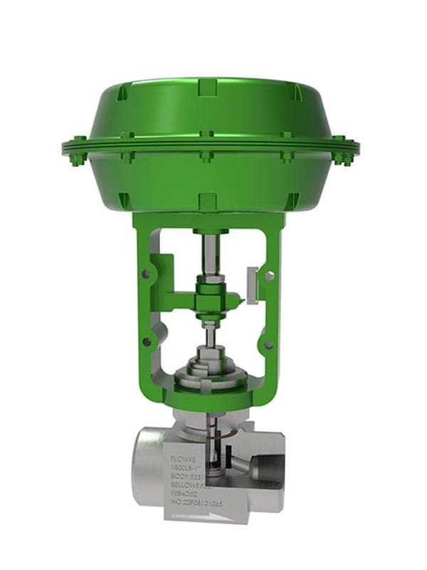
波纹管低流量调节阀

波纹管低流量调节阀

尺寸:1/2" - 1" (DN15 - DN25)

1/2”-2”Class150-2500
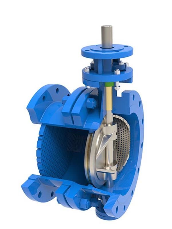
高性能三偏心控制蝶阀

高性能三偏心控制蝶阀

Quick Specs Size: 2" - 48" (DN50 - DN1200) Pressure: Class 150 - 900 Standard: API 609, API 607, ASME B16.34 Body Materials: A216 WCB, A351 CF8M, A182 F51, A182 F53 Seat Materials: Metal seat (laminated stainless + graphite, or solid metal alloy) Design: Triple offset (eccentric shaft + eccentric center + conical seal geometry), torque-sealed, friction-free engagement, 90° quarter-turn Three Offsets——and Why Two Isn't Enough A concentric butterfly valve (zero offsets) seats the disc against the liner by compressing it——the disc rotates into the seat, pushes against it, and the rubber or elastomer liner deforms to create a seal. That compression seating works for low-pressure water and air service, but it has three fundamental limitations: the disc drags across the seat surface during every open-close cycle (friction wear that degrades the liner over time), the seat relies on elastomer elasticity (temperature limits, chemical compatibility limits, aging limits), and the sealing force depends on how hard the disc pushes (limited by the actuator's torque capability and the liner's compression tolerance). A double-offset butterfly valve (also called high-performance) moves the shaft off-center in two directions——offset from the centerline of the disc face, and offset from the centerline of the pipe bore. Those two offsets let the disc lift off the seat immediately as it begins rotating——the disc cam motion separates it from the seat surface within the first few degrees of rotation, reducing friction contact to a single point at the closed position instead of dragging across the full seat face during every cycle. Better than concentric——but the seat is still an elastomer or PTFE liner, and the sealing mechanism is still compression-based. The disc presses the liner at closed position, the liner deforms to seal, and the elastomer's elasticity defines the sealing performance. You still have temperature limits, chemical compatibility limits, and aging limits. Triple offset adds the third eccentricity: the seal geometry itself is conical rather than flat. The sealing surfaces are machined on a cone angle rather than on a flat plane perpendicular to the pipe axis. That conical geometry means the disc engages the seat along the conical surface——the contact point slides along the cone's axis during the final degrees of rotation, rather than pressing flat-on-flat like concentric and double-offset designs. The result: friction-free engagement. The disc doesn't drag across the seat surface during opening or closing——it lifts off immediately (from the first two offsets) and engages the seat along the cone axis (from the third offset) without any sliding friction contact. Zero friction means zero seat wear from cyclic operation. Zero friction means the sealing force is pure torque——the actuator's closing torque pushes the disc along the cone surface until it reaches the seat, and the cone geometry converts that torque into a radial sealing force that's proportional to the applied torque rather than limited by elastomer compression tolerance. You can increase sealing force by increasing actuator torque——the seat doesn't have a compression limit because it's metal, not elastomer. That torque-sealing mechanism is what makes triple offset butterfly valves suitable for high-pressure, high-temperature, and fire-safe applications where elastomer seats can't survive. Metal Seating——No Elastomer, No Temperature Limit, No Aging Triple offset valves use metal seats——laminated stainless steel with graphite layers (the most common configuration for general high-performance service), or solid metal alloy seats for extreme temperature and corrosive applications. The laminated seat consists of thin stainless steel sheets interleaved with graphite layers——the stainless provides structural rigidity and the sealing surface, the graphite provides a conformable layer that compensates for minor surface irregularities between the disc edge and the seat face. That conformability gives laminated metal seats tighter shutoff than solid metal seats——the graphite layer fills micro-gap irregularities that solid metal-to-metal contact would leave open. But the graphite layer also defines the seat's temperature ceiling——graphite oxidizes in air above approximately 450°C, so laminated seats with graphite are limited to applications below that threshold. For higher temperatures (steam service, hot oil, thermal process loops running above 450°C), solid metal alloy seats (typically Stellite-faced or Inconel-based) provide fire-safe, temperature-unlimited sealing——tighter than elastomer, not as tight as laminated with graphite, but capable of operating at temperatures where every non-metallic seat material has failed. Fire-safe performance per API 607: the metal seating system maintains sealing integrity through fire exposure and returns to effective shut-off afterward——no elastomer or PTFE to burn away, no liner to degrade under thermal shock. On flammable gas and liquid pipelines, fire-safe certification is a regulatory requirement in most jurisdictions. Triple offset butterfly valves with metal seats achieve it by design——the seating system is already metal, already temperature-resistant, already non-combustible. Fire-safe testing confirms what the seat material choice already guarantees: the valve holds through fire because there's nothing in the seating system that fire can destroy. Large-Bore Economics——Where Butterfly Beats Gate and Ball Above 12" bore size, butterfly valves become the cost-effective isolation choice for most pipeline and process applications. A 24" gate valve weighs thousands of pounds, requires massive actuator thrust, and takes dozens of stem turns to cycle between open and closed. A 24" ball valve requires an enormous ball casting, heavy trunnion bearings, and actuator torque ratings that push the cost well above the butterfly alternative. A 24" triple offset butterfly valve weighs a fraction of either, cycles in 90° quarter-turn (seconds, not minutes), and provides metal-seated bidirectional isolation at Class 150-900 pressure ratings that cover the majority of large-bore pipeline isolation requirements. The butterfly geometry's structural advantage——a thin disc in a compact body rather than a massive gate or ball inside a heavy housing——makes the size-weight-cost relationship fundamentally favorable above 12" compared to any alternative valve type that provides the same isolation capability. FLOWKS triple offset butterfly valves cover sizes from 2" through 48"——the full range where butterfly isolation serves pipeline, process, and utility applications. The 2"-12" range overlaps with ball valve territory, where butterfly selection depends on application-specific factors (space constraints, cycling frequency, flow characteristic requirements). Above 12", butterfly dominates——the economics, the actuator sizing, and the installation logistics all favor the disc-in-body geometry over the heavier alternatives for large-bore service. FAQ What's the difference between triple offset and double offset butterfly valves?** Double offset: shaft offset in two directions, disc lifts off seat immediately on opening——reduces friction but still uses elastomer/PTFE liner seating with compression-based sealing. Triple offset: adds a third eccentricity (conical seal geometry)——friction-free engagement along the cone axis, torque-sealed metal-to-metal contact, no elastomer liner. Triple offset gives you metal seating, fire-safe capability, higher temperature range, and zero cyclic seat wear——double offset can't achieve any of these with its elastomer liner seat. Laminated metal seats (stainless + graphite layers): Class VI equivalent——bubble-tight shutoff achievable. Solid metal alloy seats: Class IV-V——tighter than elastomer, not bubble-tight, but fire-safe and temperature-unlimited. The seat configuration determines both shutoff class and the operating conditions the seat can survive. Laminated seats give the tightest shutoff up to ~450°C. Solid metal seats give fire-safe sealing at any temperature the body material can handle. Why specify triple offset instead of a gate valve for large-bore isolation? Weight, speed, and cost. A 24" gate valve weighs thousands of pounds and requires minutes to cycle——a 24" triple offset butterfly weighs a fraction of that and cycles in seconds (90° quarter-turn). The actuator torque requirements for butterfly are significantly lower than gate valve thrust requirements at equivalent bore sizes. For large-bore isolation above 12", butterfly economics (size-weight-cost-actuator) are fundamentally favorable compared to gate or ball alternatives providing the same isolation capability. What's the fire-safe certification? API 607——the valve maintains sealing through fire exposure and returns to effective shut-off afterward. The metal seating system is inherently fire-safe because there's no elastomer, PTFE, or any combustible material in the seat. Fire-safe testing confirms the design's inherent capability——the valve holds through fire because the seating system has nothing that fire can destroy. Does the triple offset design require special maintenance compared to standard butterfly valves? No——the friction-free engagement means the disc and seat surfaces experience zero sliding wear during normal cycling. The only wear mechanism is the torque-sealing contact at closed position, which is a static compression point rather than a sliding friction surface. Maintenance is simpler than double-offset or concentric butterfly valves because the seat doesn't degrade from cyclic friction——the seat's condition at the next scheduled inspection is essentially the same as at the previous one, assuming no abnormal process events have damaged the seating surfaces.

2”-48”Class150-1500
流量调节阀

流量调节阀

Quick Specs Size: 6" - 48" (DN150 - DN1200) Pressure: Class 150 - 300 Standard: IEC 60534, AWWA C504 (waterworks configurations), ASME B16.34 Body Materials: A216 WCB, A351 CF8M (stainless for corrosive water treatment) Seat Materials: EPDM, NBR, PTFE, metal hard seat (abrasive water service) Trim Design: Large-bore disc or cylinder trim, equal-percentage or linear flow characteristic Design: Rotary or linear stroke, pneumatic/electric/hydraulic actuated, optimized for high-Cv large-flow regulation Not Precision Dosing——Raw Volume Control at Scale A flow regulating valve for water treatment isn't trying to meter 0.01 gallons per minute into a reactor——it's managing hundreds or thousands of gallons per minute across treatment basins, distribution mains, and discharge channels where the flow rate matters for process performance but the regulation precision requirement is fundamentally different from chemical process control. Water treatment plants don't operate at ±0.5% flow tolerance——they operate at ±3-5% tolerance bands where the treatment chemistry works within a range, not at a point. The valve needs to move large volumes through large bore sizes, modulate the flow rate within the treatment process's acceptable range, and do it reliably under conditions that look nothing like a petrochemical refinery——municipal water supply at varying demand rates, wastewater treatment at fluctuating influent volumes, cooling water circulation at seasonal load variations, reservoir discharge at controlled release rates. These are high-Cv, large-flow applications where the valve's job is volume management, not precision chemistry. FLOWKS flow regulating valves are designed for this specific service category——large bore sizes (6" through 48"), high Cv values (the flow coefficient ratings that matter when you're moving 500 to 5000+ gallons per minute), and regulation accuracy appropriate for water treatment process requirements rather than chemical process loop tolerances. The trim geometry, the actuator sizing, and the flow characteristic profiles are all optimized for high-volume flow modulation——not borrowed from a smaller control valve design and scaled up hoping the proportions still work at DN600 bore size. The Trim——Disc or Cylinder, Depending on the Bore Size and the Regulation Requirement At smaller bore sizes within the flow regulating valve range (6"-12"), the trim uses a modified disc geometry——a contoured disc profile that provides defined flow characteristic behavior as the disc rotates through its modulating range. The disc isn't a flat butterfly plate swinging through the flow passage——it's a shaped element with a profile optimized for flow modulation, providing equal-percentage or linear characteristic behavior across the disc's rotational arc. The disc approach keeps the body compact and the actuator torque manageable at bore sizes where the disc's flow area at each rotational position can deliver the required Cv range without requiring excessive disc travel. At larger bore sizes (12"-48"), cylinder or cage-type trim becomes more practical——a cylindrical plug that moves axially within a cage to modulate flow through cage windows, similar in principle to the linear stroke control valve's plug-and-cage assembly but scaled to the larger bore dimensions and higher Cv ratings that water treatment applications demand. The cage windows define the flow area at each plug position, and the plug profile defines the flow characteristic (equal-percentage or linear) as the plug strokes through its travel range. Cylinder trim at large bore sizes provides more precise flow modulation than disc geometry——the plug-to-cage flow area relationship is more controllable than the disc-to-bore flow area relationship at DN600 and above, where the disc's rotational arc produces large flow area changes per degree of rotation that make fine modulation difficult. The trim selection (disc or cylinder) isn't arbitrary——it's determined by the bore size, the required Cv range, and the regulation precision the process demands. FLOWKS engineering specifies the trim type based on the customer's application parameters——you don't pick disc or cylinder from a catalog, you get the configuration that delivers the right flow characteristic behavior at the right bore size and Cv rating. Water Treatment Media——Not Clean, Not Corrosive-Free, Not Easy on Valve Trim Water treatment media isn't distilled water——it carries suspended solids, biological matter, chemical treatment residues, and occasionally abrasive particles from sediment load. Municipal raw water contains silt, organic debris, and seasonal sediment surges during storm events. Wastewater influent carries suspended solids, biological flocs, and chemical treatment precipitates. Cooling water circulates through systems that accumulate scale, corrosion products, and biological growth. None of this media is clean——and all of it imposes a wear and fouling burden on valve trim that chemical process applications (handling refined, filtered, specification-grade process fluids) don't face. FLOWKS flow regulating valves address the media challenge through seat material selection and trim surface treatment options appropriate for water treatment conditions. EPDM (ethylene propylene diene monomer) seats cover the majority of municipal water and wastewater applications——excellent resistance to water, mild chemicals, and biological exposure, with sufficient elasticity for tight shutoff at low to moderate pressures. EPDM's temperature ceiling (approximately 120°C) covers normal water treatment operating temperatures without approaching the limit. NBR (nitrile butadiene rubber) seats serve applications where the water contains petroleum residues or oil contamination——NBR resists oil and hydrocarbon exposure better than EPDM, but has lower chemical resistance to some treatment chemicals. PTFE seats step in where the treatment chemical concentration (chlorine, caustic, acid dosing) would degrade elastomer seats——PTFE handles the chemistry but sacrifices some of the elasticity that gives EPDM and NBR their tight shutoff capability. Metal hard seats (Stellite-faced) serve abrasive water applications——raw water intake with high sediment load, wastewater channels with entrained grit, cooling water with circulating scale particles——where soft seats would erode through before the service interval ends. Actuator Options——Pneumatic, Electric, or Hydraulic Water treatment facilities often have different actuator infrastructure than petrochemical plants——municipal waterworks may not have instrument air systems, relying instead on electric actuators powered from the plant's electrical distribution. Large-bore flow regulating valves at DN600 and above require high actuator torque——hydraulic actuators provide the force density that pneumatic and electric actuators struggle to deliver at those bore sizes without oversized, expensive actuator assemblies. FLOWKS flow regulating valves accept pneumatic, electric, and hydraulic actuator mounting——the selection depends on the facility's available infrastructure, the bore size and torque requirements, and the fail-safe positioning needs of the specific application. Pneumatic for plants with instrument air, electric for facilities without air systems, hydraulic for large-bore high-torque applications where pneumatic and electric actuator sizing becomes impractical. FAQ What's the difference between a flow regulating valve and a standard control valve? Scale and precision. A standard control valve handles small to medium flow rates with ±0.5-1% regulation accuracy in chemical process loops. A flow regulating valve handles large flow rates (hundreds to thousands of gallons per minute) with ±3-5% regulation accuracy in water treatment and utility distribution applications. The trim geometry, bore size range, and actuator sizing are all optimized for high-volume flow management rather than precision process loop control. What size range does this valve cover? 6" through 48" (DN150-DN1200)——the bore sizes where water treatment flow regulation operates. Smaller sizes use disc-type trim. Larger sizes use cylinder (plug-and-cage) trim. The trim type selection is determined by the bore size and the required flow characteristic behavior——disc for compact configurations at moderate bore sizes, cylinder for precise modulation at large bore sizes. Why EPDM seats instead of PTFE for water treatment? EPDM provides better elasticity and tighter shutoff in water service than PTFE——the elastomer deforms to fill micro-gap irregularities at the seating contact, achieving Class VI equivalent shutoff. PTFE is chemically inert but doesn't have the elasticity that gives EPDM its sealing conformability. EPDM handles normal water treatment temperatures and chemistry without degradation. PTFE steps in when the treatment chemical concentration would attack EPDM——chlorine dosing, caustic addition, acid treatment——but sacrifices some shutoff tightness for chemical resistance. Can this valve handle abrasive water with sediment? With metal hard seats (Stellite-faced seating surfaces)——yes. Soft elastomer seats erode under sustained sediment-laden flow. Metal hard seats resist abrasive wear at the cost of less tight shutoff (Class IV-V instead of Class VI). The seat material choice follows the same logic as across the FLOWKS series——match the surface to what the media will do to it. Clean water gets EPDM. Chemically treated water gets PTFE. Abrasive water gets metal hard seats. What actuator type is recommended for large-bore flow regulating valves? Depends on the facility's infrastructure and the bore size. Pneumatic for plants with instrument air——fast response, simple fail-safe. Electric for facilities without air systems——powered from the plant's electrical distribution. Hydraulic for DN600+ bore sizes where pneumatic and electric actuator torque requirements exceed practical limits——hydraulic actuators provide the force density needed for large-bore disc or cylinder trim operation without oversized actuator assemblies.

Technical Overview

Control valves don't just shut off flow—they modulate it. A ball valve opens or closes in a quarter turn; a control valve positions itself at 37%, 62%, or any point along the travel range to maintain the flow rate, pressure, temperature, or liquid level the process control loop demands. That continuous modulation is what separates throttling service from isolation service, and it dictates different trim geometry, different seat materials, different actuator response characteristics. FLOWKS manufactures linear stroke control valves with pneumatic and electric actuators for precise flow regulation across 1/2" through 12" sizes and Class 150–600 pressure ratings. V-ball control valves handle erosive, abrasive, and high-differential-pressure applications with characterised ball openings that combine shutoff capability with modulating control. Butterfly control valves—triple-offset designs—deliver tight shutoff plus throttling in large-diameter, low-pressure-drop service where linear stroke valves become impractical. Specialised configurations include self-actuated pressure regulators that operate without external power, fluorine-lined valves for concentrated acid service, bellows-sealed low-flow valves for toxic and fugitive-emission-sensitive applications, and labyrinth multi-stage pressure reduction trim that eliminates cavitation and flashing across extreme pressure drops. Every FLOWKS control valve starts with the process requirement—what media, what pressure drop, what flow characteristic, what emission standard—and builds the trim, body, and actuator configuration that matches.

FLOWKS control valves provide precise flow regulation, pressure control, and process modulation for oil & gas, petrochemical, chemical, power generation, and water treatment applications. Linear stroke control valves—pneumatic or electric actuated—deliver accurate throttling across 1/2"–12" sizes, Class 150–600, with equal-percentage or linear flow characteristics matched to process loop dynamics. V-ball control valves combine shutoff and modulating control through characterised V-shaped ball openings, with wear-resistant trim options including ceramic, hard alloy, and TCC coated configurations for erosive and abrasive service. High performance triple-offset butterfly control valves offer tight shutoff plus throttling capability in large-diameter, low-pressure-drop applications. Self-actuated pressure regulating valves operate without external power—process pressure itself drives the actuation mechanism for simple, reliable pressure control. Fluorine-lined control valves handle concentrated acid and aggressive chemical media where metal trim would corrode. Low flow regulating valves—including bellows-sealed configurations—provide precise trace-quantity regulation for analytical, sampling, and fugitive-emission-critical service. Labyrinth multi-stage pressure reduction control valves eliminate cavitation and flashing across extreme differential pressure drops through staged energy dissipation within the trim. Flow regulating valves optimise water treatment and distribution system performance with low-pressure-loss disc designs. FLOWKS control valves meet IEC 60534, ISO 15848, and API 608 standards with multiple body materials and trim configurations for every process condition.