products.productRange
适用于各种应用的完整工业阀门系列。
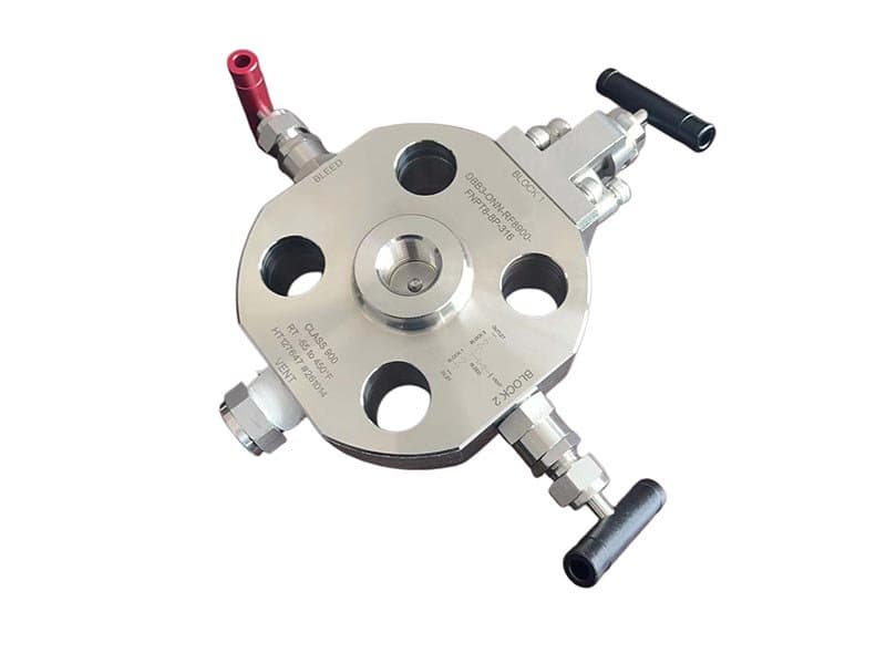
仪表管阀块-无法兰DBB
1/2英寸 - 2英寸(DN15 - DN50)Class 150 - 1500 / 最高10,000 psi(针阀式配置)API 6D、API 607、ASME B16.34、ISO 15848 A182 F316、A182 F51、A182 F53 PTFE、PEEK、金属对金属(Stellite 6)仪表阀组阀体,带无法兰连接,双关断与排放配单个排放口,紧凑型仪表阀 仪表阀组DBB的作用——以及仪表工程师为何指定选用它 压力表、变送器和仪表接口需要隔离,以便在不关闭主工艺管线的情况下进行校准、更换和验证。这种隔离必须是双重的——当工艺管线承载1500 psi碳氢化合物或10,000 psi液压油时,一个阻断阀座是不够的。单个阀座可能泄漏。单个阀座可能失效。如果发生这种情况,工艺介质会同时到达仪表和排放口——技术人员在试图验证零压力时会被活体工艺压力冲击。这就是为什么API 6D对双关断与排放的定义要求两个独立密封边界,并在两者之间设有排放腔:第一个阀座阻断上游压力,第二个阀座阻断朝向仪表的下游压力,两个阀座之间的排放腔提供一个经过验证的零压力区域,你可以在打开仪表侧之前确认两个阀座均处于密封状态。仪表阀组DBB阀将两个阻断阀座和排放腔集成到一个紧凑的阀体中,直接安装在仪表连接点——无需单独的阀门、无需三通接头组件、无需在阻断和排放功能之间存在多个潜在泄漏路径。 无法兰——无法兰、无螺栓、直接螺纹安装 无法兰连接意味着阀体直接旋入仪表连接点——通常是管道或容器壁上的1/2英寸或3/4英寸NPT螺纹接口——阀与工艺之间无需任何法兰螺栓连接。这种直接螺纹安装消除了法兰垫片作为潜在泄漏路径的可能性(法兰在垫片处泄漏;螺纹连接没有垫片),缩小了安装空间(无法兰螺栓分布圆、无垫片对中、无螺栓张紧程序——只需将阀门旋入接口并用扳手拧紧),并将整体装配高度降至仪表安装所需的最小实际尺寸。法兰式仪表阀组DBB也存在(FLOWKS也生产此类产品——参见法兰式DBB系列),适用于仪表连接点为法兰而非螺纹的应用。但对于工艺管道上的大多数仪表接口——即焊接在主管线上的NPT螺纹管座——无法兰版本是更简单、更紧凑、更直接的安装选项。无需螺栓连接法兰。无需对中垫片。无需执行法兰螺栓程序。旋入。扳手拧紧。完成。 紧凑的阀体几何结构是功能性要求,而非外观偏好。仪表安装的物理空间有限——压力表或变送器安装在阀门末端,两者都必须容纳在管廊或容器裙座净空范围内。采用无法兰螺纹连接的仪表阀体,可将总装配长度(从工艺连接到仪表法兰或螺纹)保持在既能容纳两个切断阀座又能容纳排放腔的最小尺寸。较短的装配长度意味着从管壁突出的部分更少,在拥挤的管廊区域中受维护作业撞击损坏的风险更低,同时对螺纹管座的重量也更小(螺纹连接承受装配重量带来的弯曲载荷——更短更轻意味着螺纹啮合处的弯曲应力更低)。 双阀座加排放口——DBB隔离的功能架构 仪表阀体包含两个独立的密封元件,沿流路串联布置——上游(工艺侧)阀座和下游(仪表侧)阀座。每个阀座独立密封:上游阀座阻止工艺压力进入两阀座之间的排放腔,下游阀座阻止可能泄漏通过上游阀座的任何压力到达仪表连接处。排放口位于两阀座之间——一个小直径端口(通常为1/4英寸NPT),将腔体排放至大气或封闭排放系统。操作中:两阀座关闭,排放阀打开——排放口验证阀座间腔体零压力,确认两个截止边界均保持密封。若上游阀座泄漏,工艺压力进入腔体并通过排放口排出——技术人员在排放口看到活压力,即知上游阀座未保持密封。若下游阀座泄漏,腔体压力(如有)到达仪表侧——技术人员在仪表连接处看到压力,即知下游阀座未保持密封。排放口使阀座完整性可见且可验证——你不假设两个阀座都在密封,而是通过打开仪表侧前检查排放口压力来验证。 两个阀座不共享任何常见失效模式——它们是独立的密封元件,具有独立操作机构(上游阀座在上游阀杆旋转至关闭位置时关闭;下游阀座在下游阀杆旋转至关闭位置时关闭;排放口在排放针阀阀杆退离其阀座时打开)。单点失效(一个阀座泄漏)不会损害另一阀座的密封完整性——剩余阀座仍阻止来自失效侧的压力,排放口排放腔体以揭示哪个阀座已失效。这种独立性是DBB相对于单截止隔离的根本安全优势:一个阀座可能失效,系统仍通过剩余阀座提供已验证的隔离,并通过排放口提供失效的可见证据。 阀座材料选项——PTFE、PEEK和金属对金属,适用于不同工艺条件 聚四氟乙烯(PTFE)阀座:中等温度和压力下通用仪表隔离的标准选择。PTFE 阀座具有良好的密封性(可达到 VI 级),摩擦力低,并且与碳氢化合物、水、蒸汽和化学工艺介质具有广泛的化学兼容性。PTFE 的耐温上限(约 200°C)涵盖了大多数仪表测口的工作温度,这些测口通常安装双球阀座(DBB)。聚醚醚酮(PEEK)阀座适用于高温和高机械应力应用——在 PTFE 因持续载荷而软化和变形的温度下,以及在 PTFE 机械强度接近极限的高压等级下,PEEK 阀座仍能保持尺寸稳定性和密封面完整性。金属对金属阀座(球体和阀座密封面采用司太立合金 6 硬面堆焊)适用于高压、高温和腐蚀性介质应用,在这些应用中,软质阀座无法承受——金属阀座可达到 IV 级泄漏等级(并非完全密封,但在会破坏 PTFE 和 PEEK 的条件下仍能保持耐用性)。座圈材料的选择遵循与 FLOWKS 产品系列相同的工艺匹配逻辑:使密封表面与介质和运行条件在预期使用寿命内对其产生的影响相匹配。 无法兰连接:直接通过 NPT 螺纹连接到仪表接口——无需法兰螺栓、垫片,组件长度最短。法兰连接:阀门与仪表之间采用法兰连接——适用于仪表接口为法兰连接而非螺纹连接的应用,或为便于维护而指定采用法兰连接的应用。功能架构相同(双阀座 + 泄放腔),连接接口不同。 单阀座隔离提供一个截止边界。若该单阀座泄漏,工艺压力同时到达仪表和排放口——技术人员会遭受活工艺压力冲击。DBB提供两个独立截止边界,其间有已验证的零压力腔体。若一个阀座失效,另一个仍起阻断作用,排放口揭示哪个阀座已失效。两个阀座并非冗余——它们是独立的,具有独立失效模式,并通过排放腔提供可见验证。 法兰连接版本涵盖Class 150至Class 1500。螺纹连接的针阀型配置最高可达10,000 psi——紧凑的阀体几何结构和锻制材料结构可在小口径尺寸下承受高内部压力,而在此类尺寸下法兰压力等级已超出仪表连接尺寸的实际限制。 它将两个阻断阀座之间的腔体排放至大气或密闭排放系统。当两个阀座均关闭且排放阀打开时,排放口处零压力确认两个阀座均密封良好。如果工艺压力出现在排放口,则上游阀座泄漏。如果压力出现在仪表接口处,则下游阀座泄漏。排放口使阀座密封性可见——您验证隔离,而非假设其有效。 是的——API 607防火认证可选配金属对金属阀座(Stellite 6)。PTFE和PEEK阀座在火灾暴露中会烧毁;金属阀座在火灾中保持密封,并在事后恢复有效关断。对于安装在可燃气体和液体工艺管线且要求防火隔离的场合,金属阀座是强制规格。
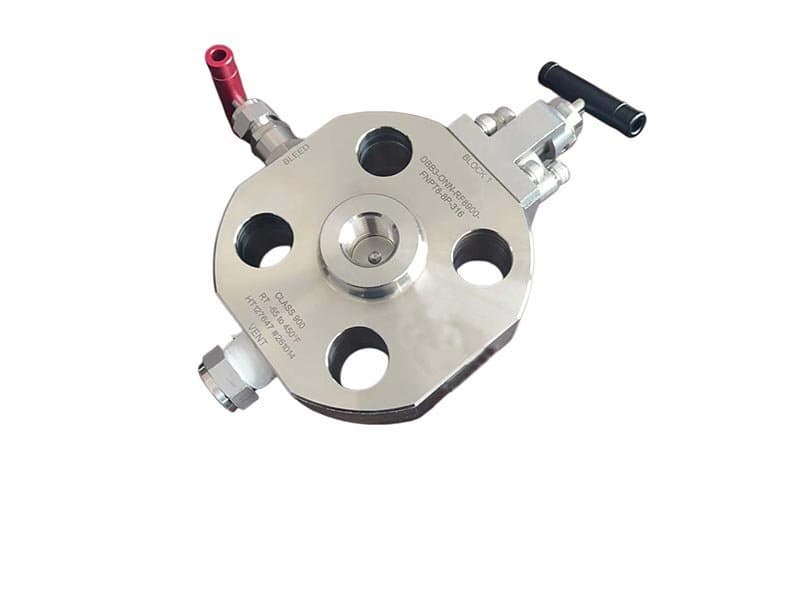
仪表管阀块-无法兰SBB
1/2" - 2" (DN15 - DN50) 150 - 1500 级 / 最高 10,000 psi(针阀式) API 6D、API 607、ASME B16.34、ISO 15848 A182 F316、A182 F51、A182 F53 PTFE、PEEK、金属对金属(司太立 6) 压力表阀体,无法兰连接,单阀体带泄放阀和泄放验证口,紧凑型仪表阀 SBB与DBB——一个阀座或两个,以及何时一个足够 双阻断与排放(DBB)提供两个独立密封边界,并在其间设有经验证的零压力腔体——这是单个阀体所能提供的最大隔离保障。但并非每个仪表隔离应用都需要最大保障。某些应用需要带排放检查的验证隔离,但工艺条件不要求两个独立阻断边界:低压公用管线、非危险介质(水、空气、氮气)、非易燃工况下的仪表接管,其中单个阀座泄漏的后果是仪表读数误差,而非安全事故。对于这些应用,单阻断与排放(SBB)提供一个阻断阀座和一个排放验证口——足以安全拆除仪表(阀座阻断工艺压力,排放口在仪表侧打开前验证阀座密封良好),但仅有一个密封边界而非两个。权衡很直接:一个阀座而非两个意味着更少组件、更短装配长度、更低成本和更简单操作——但只有一个阻断边界,而非两个独立边界。如果该单个阀座失效,则没有备用阀座维持隔离。排放口会揭示失效(工艺压力出现在排放口),但隔离能力已丧失,直到阀座修复。 FLOWKS SBB 压力表阀采用与 DBB 型号相同的紧凑型阀体几何结构——非法兰螺纹安装、直接 NPT 连接至仪表接口、最小装配高度——但只有一个阻断阀座,而非两个。泄放口位于单个阻断阀座的下游侧,提供验证功能,使 SBB 区别于不带泄放功能的简单单阻断隔离阀。当阻断阀座关闭且泄放阀打开时,泄放口处的压力为零,表明单个阀座保持密封。如果泄放口处出现过程压力,则表明阀座失效——隔离失效,仪表侧暴露于实际过程压力下。正是这种验证功能(在打开仪表侧之前进行泄放检查)使得 SBB 比不带泄放功能的简单单阻断阀更安全——技术人员不会假设阀座保持密封,而是通过泄放口进行验证。但它仍然只有一个阀座——如果验证发现失效,则没有备用阀座。 SBB何时是合适的规格——以及何时不合适 SBB与DBB之间的决策并非关乎偏好或成本优化——而是关乎后果分析。如果单个阻断阀座泄漏或失效会发生什么?如果后果是非危险公用管线上的仪表读数误差或变送器校准漂移——SBB足够。排放口揭示失效,维护人员更换阀座,工艺继续运行。如果后果是暴露于有毒、易燃或高压介质,从而造成安全事故或环境泄漏——DBB是强制性的。SBB中的单个阀座在密封良好时提供验证隔离,但在失效时不提供备用。在危险工况下,这是不可接受的——DBB中的第二个阀座提供备用,即使第一个阀座失效也能维持隔离,且排放腔体揭示哪个阀座失效而不丧失整体隔离能力。 在碳氢化合物、化学品和高压管道的工艺隔离方面,监管框架和行业标准越来越多地默认采用双阻断泄放(DBB)方式——API 6D对双阻断泄放的定义是易燃和有毒介质新安装的基准规范。单阻断泄放(SBB)仍然适用于非危险公用设施(仪表空气、氮气保护、低压水、暖通空调系统),在这些应用中,隔离的后果只是操作上的不便,而非安全风险。在这些应用中,SBB更简单的架构(一个阀座、一个泄放口、更少的组件、更短的装配)可提供经过验证的隔离,并具有足够的安全裕度——由于单个阀座失效的后果较轻,因此取消第二个阀座所降低的成本和复杂性是合理的。 排放口——相同的验证功能,位置在一个阀座之后而非两个之后 在DBB阀门中,排放口位于两个阻断阀座之间——它排放两者之间的腔体,并同时验证上游和下游阀座均在密封。在SBB阀门中,排放口位于单个阻断阀座的下游——它排放阀座与仪表连接之间的空间,并在仪表侧打开前验证单个阀座正在密封。两种配置的验证程序相同:关闭阻断阀座,打开排放阀,检查排放口处压力为零。零压力确认阀座正在密封。排放口处有活压力则表明阀座失效。区别在于DBB同时验证两个独立阀座,而SBB验证一个阀座——验证揭示的真相相同(阀座密封状态),但揭示失效后的后果不同(DBB由剩余阀座保持隔离;SBB完全失去隔离)。 SBB配置中的排放口具有次要功能:在仪表拆卸前排放阀座与仪表连接之间截留的压力。即使阀座密封完美,关闭的阀座与关闭的仪表连接之间截留的残余压力(来自先前工艺暴露、热膨胀或仪表泄压)在仪表法兰或螺纹拆卸前需要排放路径。排放口提供该排放通道——技术人员打开排放阀,截留压力安全排放,仪表在连接侧零残余压力的情况下被拆卸。该排放功能独立于阀座验证功能——排放口在阀座密封时排放截留压力,在阀座未密封时揭示阀座失效。两种功能,一个端口。 紧凑型仪表几何结构——相同安装,比DBB更短 SBB阀体比DBB阀体短,因为它容纳一个阻断阀座而非两个——第二个阀座组件的消除使阀体长度减少了两个阀座位置之间的距离。在物理间隙紧张的仪表安装中(管廊拥挤、容器裙座干涉、管壁突出空间有限),较短的阀体尺寸可能决定阀门是否适合安装。非法兰螺纹连接保持与DBB版本相同的安装接口——仪表接头上相同的NPT螺纹啮合,相同的直接安装方式,相同的法兰螺栓和垫片消除。区别纯粹在于内部阀座结构:一个阀座而非两个,更短的阀体,螺纹管座上更轻的重量。 SBB:一个阻断阀座+一个排放验证端口。DBB:两个阻断阀座+两者之间的一个排放口。SBB提供来自一个阀座的已验证隔离——排放确认阀座正在密封,但如果失效,没有备用。DBB提供来自两个独立阀座的已验证隔离——如果一个失效,另一个保持隔离,排放口揭示哪个失效。SBB适用于非危险工况,其中单阀座失效后果是操作性的,而非安全相关的。DBB是危险工况的强制要求,其中单阀座失效后果是安全事故。 DBB阀体比SBB阀体长(它容纳两个阀座而非一个)。如果安装有足够间隙容纳较长的DBB组件,升级就是简单的阀门更换——相同的非法兰NPT螺纹安装接口,相同的仪表连接点,只是更长的阀体带两个阀座而非一个。如果间隙无法容纳较长的DBB阀体,SBB配置是该安装的物理极限——空间只允许一个阀座时无法容纳两个。 通常情况下,1/4” NPT 是 DBB 和 SBB 压力表阀的标准仪表排气接口尺寸。排气口可连接标准针阀、排气塞或通向大气或封闭式排水口的排气管。无论阀门是 DBB 还是 SBB,连接方式都相同。 金属对金属阀座(Stellite 6)——是的,可提供API 607防火安全认证。PTFE和PEEK阀座在火灾暴露中烧毁;金属阀座在火灾中保持密封。对于防火安全不是法规要求的非危险工况,PTFE或PEEK阀座提供足够的性能。对于易燃工况的安装(即使低压),无论阀门是SBB还是DBB,金属阀座都是正确的规格。 因为已验证隔离比假设隔离更安全。没有排放口的简单隔离阀在仪表侧打开前无法提供任何确认阀座密封的方法。技术人员基于阀门位置指示器假设阀座正在密封——但位置指示器可能出错,即使阀杆指示关闭,阀座也可能泄漏。SBB中的排放口提供直接、可见的验证方法——打开排放,检查为零,在继续前确认阀座实际密封。该验证步骤只需几秒钟,消除了隔离完整的假设。
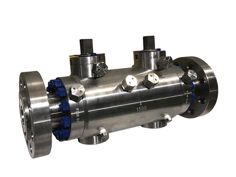
固定球双阻断与排放DBB
关于耳轴式双阻断与排放DBB 2英寸-24英寸(DN50-DN600) API 6D、API 607、ASME B16.34、ISO 15848 A216 WCB、A351 CF8M、A182 F51、A182 F53 PTFE、尼龙、PEEK、金属对金属(Stellite 6) 耳轴安装球体带弹簧加载阀座,单阀体双阻断与排放,侧入式或顶入式维护通道 不信任单个阀座的管道隔离——因为管道后果不允许这样做 管道隔离阀位于输送碳氢化合物、化学品或高压气体的工艺管线区段之间——在这些介质中,隔离失效的后果不是仪表读数误差,而是安全事故、环境泄漏或违规行为。在这些应用中,一个阻断阀座即使处于密封状态也不够——因为该阀座失效的后果是不可接受的。单阻断阀仅提供一个密封边界进行隔离;如果该边界泄漏,介质将到达本应被隔离的下游区段。耳轴式DBB阀通过两个独立的密封边界提供隔离,并在两者之间设有经过验证的零压腔体——上游阀座阻断来自活跃管线区段的压力,下游阀座阻断朝隔离区段的压力,而两个阀座之间的排放腔体则提供一个经过验证的零压区域,在下游区段被打开进行维护、检查或热开孔操作之前,确认两个阀座均处于密封状态。两个独立阀座,两种独立失效模式,一个通过排放口可见的已验证隔离状态。 耳轴安装式球阀结构为单个阀体内的两个独立弹簧加载阀座提供了结构平台。球体由上、下耳轴销锚定——它不像浮动球阀那样在压差下浮动。两个阀座环位于球体相对两侧,各自独立地通过弹簧压紧在球体表面。当球体旋转至关闭位置时,两个阀座同时密封——上游阀座针对上游压力,下游阀座针对下游压力,两者独立,均可通过排放腔体验证。这种耳轴结构使DBB在大口径规格下得以实现——浮动球阀只有一个密封方向(球体在上游压力下推向下游阀座),而耳轴阀有两个独立密封方向(每个弹簧加载阀座从自身一侧推压球体)。两个阀座。两个弹簧。两个独立密封力。一个位于两者之间的已验证隔离腔体。 为什么耳轴式DBB取代旧的三阀组件 在单体DBB阀成为标准管道隔离规范之前,行业使用三个独立阀门来实现双阻断和排放:两个隔离阀(一个上游、一个下游)和一个位于两者之间三通接头中的排放阀。这种三阀组件有效——它提供两个阻断边界和一个排放验证口——但它有四个固有问题,而单体耳轴式DBB消除了这些缺陷。 第一:多个潜在泄漏路径。三个阀门意味着三个阀体、三套阀体与管道连接、三个阀盖与阀体垫片,以及三个阀门之间的三通接头连接——每个连接都是潜在的外部泄漏路径。单体DBB消除了所有阀间连接——两个阻断阀座和排放口都在一个阀体内,阻断与排放功能之间没有外部连接,只有一个通向大气或排放管的排放口。更少的外部连接意味着更少的潜在泄漏路径。 第二:更大的安装空间。三个独立阀门加一个三通接头所占用的管架空间明显大于单体DBB——三阀组件的长度是两个隔离阀加三通接头的组合长度,而单体DBB则适配在单个阀体长度内。在空间分配受限的拥挤管架安装中,单体DBB的紧凑占地面积是一个超越美观的实际优势。 第三:更高的总重量。三个阀体加一个三通接头比一个DBB阀体更重——管架上的钢材更多,管道支架上的重量更大,结构载荷更高。减重不仅仅是便利问题——在大口径管道安装中,三阀组件与单体DBB之间的重量差异可能影响管道支架设计和应力分析计算。 第四:顺序操作的复杂性。操作三个独立阀门需要特定顺序:关闭上游隔离阀,打开排放阀,在排放口验证零压,关闭下游隔离阀,然后进行下游作业。该顺序每次都必须正确执行——任何顺序错误(先关闭错误的阀门、在验证期间打开错误的阀门)都可能使下游区段暴露于活态工艺压力。单体DBB阀通过一个执行器关闭球体(两个阀座同时密封)和一个验证腔体的排放阀进行操作——操作更简单,步骤更少,顺序错误的机会更小。 排放口配置——通向大气排放或封闭排放管 两个阻断阀座之间的排放腔体通过阀体上的指定端口排放——通常为1/2英寸或1英寸法兰或螺纹连接。两种排放配置:大气排放(排放口通过针阀或堵头直接通向大气——用于非危险工况,少量排放至大气可接受)和封闭排放管(排放口连接到封闭排放系统,收集排放的介质——用于危险、易燃或受环境法规监管的工况,禁止向大气排放)。排放口配置根据工艺介质特性和设施的环保排放法规来指定——你不能将H₂S或VOC排放至大气,而是将其收集在封闭排放系统中。在非危险公用工程工况下,通过针阀进行大气排放是标准做法。 ISO 15848低泄漏认证——DBB隔离与逸散性排放合规 耳轴式DBB阀上的阀杆密封系统遵循与FLOWKS耳轴式球阀系列相同的低泄漏设计理念——采用石墨填料配合弹簧加载压盖设计,以满足ISO 15848合规要求。阀杆从阀盖与阀体接口处伸出阀体——这是阀门压力边界唯一的外部穿透点,也是填料密封效果不佳时逸散性排放可能泄漏的位置。ISO 15848根据阀门的认证等级(BH、AH或CH,对应不同温度和循环条件)定义了可接受的排放率。FLOWKS耳轴式DBB阀设计用于满足ISO 15848排放要求——填料系统、压盖加载机构以及阀盖与阀体间的垫片均按额定温度和压力条件下的低泄漏性能进行规定。在受环保法规管控的工艺管线上(VOC排放限值、H₂S暴露阈值),ISO 15848认证并非可选升级——而是由法规合规性驱动的规格要求。 尺寸与应用。仪表阀组DBB阀是紧凑型仪表阀门(1/2"-2"通径),用于仪表隔离——直接螺纹安装于仪表和变送器连接点。耳轴式DBB阀是管道隔离阀(2"-24"通径),用于运行管段与维护管段之间的区段隔离——全通径或缩径流道,法兰或对焊连接至管道,执行器驱动以实现自动化隔离程序。相同的DBB功能架构(两个阀座+排放腔),不同的规模和不同的应用场景。 浮动球阀单向密封——球体在上游压力作用下向下游浮动并压紧下游阀座。这种单向密封提供一个阻断边界,而非两个独立边界。耳轴安装的球体通过上下销轴固定球体——两个阀座环分别从相对侧独立弹簧加载压紧球体。每个阀座在其各自方向上独立密封。这种双向独立密封是实现真正DBB隔离的结构要求——两个独立边界,两种独立失效模式,通过两者之间的腔体进行验证。 软阀座(PTFE、Nylon、PEEK)——两个阀座均可达到Class VI(气泡级密封)。金属对金属阀座(Stellite 6)——两个阀座均为Class IV,非气泡级密封,但在冲蚀性和高温条件下耐用。阀座材料选择独立决定每个阀座的关断等级——两个阀座使用相同的材料规格,但每个阀座的密封性能通过排放腔分别验证。 1/2"或1"——法兰或螺纹连接,取决于阀门通径大小和工厂排放系统连接标准。较小通径的DBB阀通常使用1/2"螺纹排放口。较大通径的DBB阀(8"以上)通常使用1"法兰排放口,以适应阀座在满管线压力下失效时可能产生的更高排放流量。 是的——API 607防火认证,采用金属对金属阀座(Stellite 6)。软阀座在火灾中烧毁;金属阀座在火灾中保持密封并在事后恢复有效关断。在易燃气体和液体管线上,API 607防火认证是法规要求——金属阀座是强制性的,而非可选项。
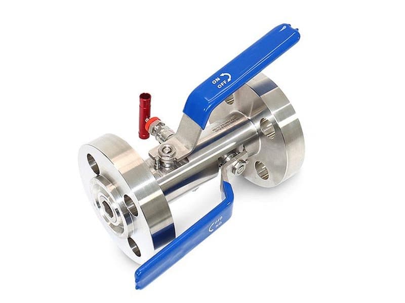
法兰双阻断排放阀DBB
关于法兰块-排放DBB 快速规格 2" - 20"(DN50 - DN500) Class 150 - 600 API 6D、API 607、ASME B16.34、ISO 15848 A216 WCB、A351 CF8M、A182 F51 PTFE、Nylon、PEEK、金属对金属(Stellite 6) 法兰端连接(RF/RTJ)、螺栓连接阀盖、单阀体双阻塞与排放、手动或执行器操作 法兰连接——当管道规格要求螺栓端连接时 法兰式DBB阀与耳轴式DBB阀实现相同的隔离功能——两个独立阻断阀座,中间带可验证的排放腔——但采用法兰端连接至管道而非对焊。法兰连接(按ASME B16.5的突面或环连接面)是许多工厂规格中Class 150至Class 600的标准管道连接方式——特别是在维护可达性要求螺栓连接(无需切割和重新焊接管道即可拆卸)的工艺管道系统上。对焊DBB阀(如FLOWKS全焊接DBB系列)将阀门永久连接至管道——拆卸需要切割焊缝并重新焊接替换件。法兰式DBB阀可从管道法兰上卸下螺栓——每个法兰四颗螺栓(较小尺寸)或较大尺寸上的数十颗,但原理相同:卸螺栓、拆除、更换、重新紧固。无需焊接。无需动火作业许可证。无需对替换焊缝进行射线检测。 这种螺栓连接的便利性是工厂在Class 150-600管道上指定法兰式DBB阀的主要原因——在法兰连接结构上足够的压力等级下,螺栓连接的维护物流比焊接连接更简单、更快、更经济。在Class 600以上,对焊连接成为标准规格,因为Class 900及以上的法兰连接需要更重的螺栓、更大的垫片表面和更高的螺栓张紧载荷,这使得法兰连接的维护复杂性在许多安装中超出实际可行范围。FLOWKS法兰式DBB覆盖Class 150至Class 600——这一压力范围正是法兰连接服务于大多数工艺管道安装的区间,也是螺栓连接维护优势最具价值的区间。 螺栓连接阀盖——无需将阀门从管道上拆下即可进行维护检修 阀盖(包含阀杆、填料和上耳轴轴承的阀体部分)通过螺栓连接的阀盖与阀体连接——螺栓连接,而非焊接。这种螺栓式阀盖设计使得在不将整个阀门从管道法兰上拆卸的情况下,即可对阀杆填料、上耳轴轴承以及球体和阀座组件进行维护。维护流程:拆下阀盖螺栓,将阀盖组件(阀杆、球体上销、填料)从阀体中提起,接触阀座环和球体进行检查或更换,用新垫片重新安装阀盖,重新拧紧螺栓,重新施加扭矩。管道法兰保持连接——整个维护过程中阀体始终与管道保持连接。这种在线维护能力与FLOWKS顶装式球阀用于埋地和焊接管道服务的原理相同——区别在于法兰式DBB的螺栓阀盖服务于法兰连接安装,其中管道法兰本身是主要拆卸点,而阀盖螺栓是内部阀件维护的次要检修通道。 阀盖与阀体之间的垫片是关键的密封元件——它是阀体腔(承受管道压力)与阀盖腔(接触填料和阀杆)之间的压力边界。垫片规格需匹配工艺介质和温度条件:螺旋缠绕垫片(不锈钢缠绕层配石墨或PTFE填料)适用于一般工艺服务,金属环垫片适用于高温和防火应用,在这些场景下螺旋缠绕垫片会在持续热载荷下退化。每次拆卸阀盖时都必须更换垫片——垫片是一次性密封元件,不可重复使用。这一更换要求是螺栓式阀盖阀门设计的标准维护实践——你不能在压力边界上重复使用垫片,每次重新组装接头时都要安装新的。 双阻塞与排放——相同的功能架构,法兰安装形式 法兰阀体内部的DBB隔离架构与耳轴式DBB相同:两个独立的弹簧加载阀座从相对两侧压紧安装在耳轴上的球体,两者之间有一个排放腔,通过阀体上的指定端口排放。上游阀座阻断来自活跃管道段的工艺压力。下游阀座阻断通向隔离段的压力。排放腔同时验证两个阀座——排放口压力为零确认两个阻塞边界均保持密封。无论连接类型(法兰或对焊)如何,功能行为相同:阀座密封,排放验证,隔离是双重且独立的。 法兰式DBB与对焊式DBB的区别完全在于安装接口——法兰端用于螺栓连接的管道连接,便于维护检修;对焊端用于永久性管道集成,具有最大的结构完整性和最少的外部泄漏路径。两种配置提供相同的DBB隔离性能。两者之间的选择由设施的管道规范(该尺寸和压力等级下管线使用法兰还是焊接连接?)、维护理念(是否要求在线拆卸还是倾向于永久安装?)以及具体应用的结构和法规要求决定。 法兰式DBB:螺栓连接端(RF/RTJ法兰)——可通过松开螺栓从管道上拆卸,无需切割管道。对焊式DBB:焊接连接端——与管道永久连接,拆卸需要切割焊缝。阀体内部提供相同的DBB隔离功能。法兰式适用于Class 150-600管道的维护检修便利性。对焊式适用于Class 900以上管道或埋地服务的永久安装和最小外部泄漏路径。 在Class 600以上,法兰连接需要更重的螺栓、更大的垫片表面和更高的螺栓张紧载荷,这使得法兰维护不如对焊实用。对焊连接是Class 900-1500管道的标准规格——在这些压力等级下,焊接接头的结构完整性和泄漏路径消除优势超过了法兰连接的维护检修便利性。FLOWKS为Class 900-1500应用提供对焊式和全焊接式DBB配置。 无需将阀门从管道法兰上拆卸即可在线检修阀杆填料、耳轴轴承和阀座/球体组件。拆下阀盖螺栓,将其提起,检修内部件,用新垫片重新拧紧。管道全程保持连接——无热作业、无切割、无重新焊接。这种可检修性是螺栓式阀盖设计相对于焊接式阀盖设计的维护优势。 是的——API 607认证,配金属对金属阀座(Stellite 6)。带RTJ垫片的法兰连接在火灾暴露期间与阀体的金属密封面一起保持密封性能。在易燃服务管道上,无论连接类型如何——法兰或焊接——防火认证都是强制性的,密封系统必须在火灾中保持密封。 阀体上采用1/2英寸或1英寸法兰或螺纹连接——根据工艺介质排放至大气或封闭排放系统。危险介质(H₂S、碳氢化合物、VOC)需要封闭排放收集。非危险公用工程服务通过针阀排放至大气。排放口尺寸随阀门通径变化——较大通径使用较大的排放口,以适应阀座失效条件下更高的潜在排放流量。
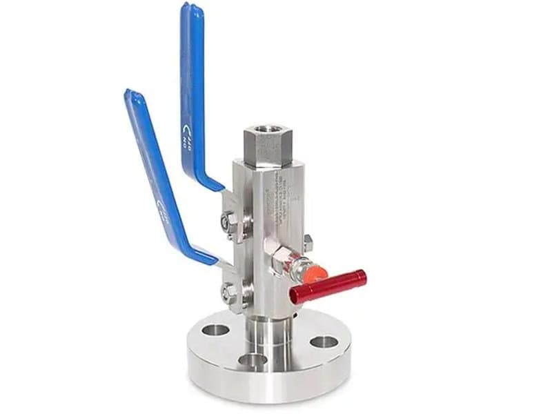
法兰对螺纹针型DBB阀
快速规格 1/2" - 1"(DN15 - DN25)最高10,000 psi(相当于Class 150 - 2500) API 6D、API 607、ASME B16.34、ISO 15848 A182 F316、A182 F51、A182 F53 PTFE、PEEK、金属对金属(Stellite 6)法兰式工艺侧连接 + 螺纹(NPT)仪表侧连接,针型DBB紧凑阀体,带单个排放口的双关双断 一端法兰,另一端螺纹——管道采用法兰连接,而仪器采用螺纹连接。 在仪表连接点,工艺管道通常一侧采用法兰式隔离阀,另一侧采用螺纹(NPT)连接——管道规范要求内径大于1英寸的管道采用法兰连接,以确保结构完整性和维护便利性,但仪表连接(仪表、变送器、压力开关)几乎总是采用1/2英寸NPT螺纹连接,因为仪表本身没有法兰连接。这种连接方式的不匹配——一侧法兰,另一侧螺纹——正是此阀门所要解决的问题。工艺侧(上游)连接采用法兰连接(符合ASME B16.5标准的RF或RTJ),直接用螺栓固定到管道法兰上。仪表侧(下游)连接采用NPT螺纹接口,仪表或变送器直接旋入该接口。在法兰式上游连接和螺纹式下游连接之间设有两个阻流阀座和一个泄放腔——DBB隔离阀的功能覆盖了从法兰式管道接口到螺纹式仪表接口的整个流路,两者之间无需任何额外的接头、适配器或互连泄漏路径。 如果没有这种法兰螺纹连接方式,安装人员就必须拼凑一个法兰隔离阀、一个异径接头(法兰螺纹适配器)和一个单独的泄放阀——这三个部件有两个连接点(法兰到适配器,适配器到仪表),这两个连接点都可能成为外部泄漏路径。每个连接点都需要增加一个垫片或螺纹密封件,并且需要单独维护。而法兰螺纹针式双端泄放阀 (DBB) 则消除了这两个连接点——法兰端直接用螺栓固定在管道上,螺纹端直接连接仪表,DBB 隔离阀位于两者之间的单个阀体内部。无需适配器,无需额外接头,也不存在连接泄漏路径。一个阀体即可解决所有连接不匹配的问题。 针型——用于高压仪表引出点的紧凑阀体 针阀式阀座是指其采用针阀式阀芯而非球阀式阀芯——即锥形针塞嵌入与之匹配的锥形阀座环中,而不是旋转球体与平面或弧形阀座环密封。针阀式阀芯在小孔径和高压工况下具有两个实际优势: 首先,针锥阀座的密封性能是渐进式的——随着关闭力的增加,针阀会更深地嵌入锥体,形成线接触密封,并随着阀杆扭矩的增加而进一步收紧。这种渐进式密封特性使针阀在高压下具有机械优势,而球阀阀座(依靠特定阀座几何形状的表面接触)在1500级以上的压力下难以保持完全密封。针阀的锥形几何形状会产生楔入效应——施加的关闭扭矩越大,针阀楔入锥体的程度就越大,密封性能会逐渐增强,而不是达到由阀座弹性变形决定的极限。 其次:针阀组件的紧凑几何形状使其能够安装在比相同孔径的球阀阀体更小的阀体内——在 1/2 英寸孔径下,针阀组件(阀杆、锥形阀芯、阀座)占用的内部容积小于球阀组件(球体、两个阀座环、轴颈销)。这种紧凑的几何形状使得阀体整体尺寸更小、重量更轻——这对于管道接口空间有限的仪表安装至关重要,因为管道接口处的空间有限,而且法兰连接处的重量必须控制在法兰的结构承载能力之内。 针式双阻断阀 (DBB) 中的两个阻断阀座是两个独立的针阀组件——一个上游(工艺侧)针阀和一个下游(仪表侧)针阀,每个针阀都有自己的阀杆、阀座锥和操作手柄。泄放口位于两个针阀座之间——这是一个较小的第三针阀,用于排出两个阻断针之间的空腔内的气体。三个阀杆、三个手柄、一个阀体。每个针阀独立操作——先关闭上游针阀,打开泄放针阀以确认零位,然后再关闭下游针阀。操作顺序与任何双阻断阀 (DBB) 的操作相同,但其阀座机构为针锥式,而非球环式。 两个针和一个排放口——独立密封、独立验证 上游阀针阻断法兰管道连接处的工艺压力。下游阀针阻断任何可能从上游阀针泄漏到螺纹仪表连接处的压力。泄放阀针将两个阻断阀针之间的空腔排气至大气或封闭式排水口。DBB 验证逻辑相同:关闭两个阻断阀针,打开泄放阀针,检查泄放阀针处的压力是否为零——零压力表示两个阀针均保持密封。泄放阀针处的压力为零表明上游阀针失效。仪表连接处的压力为零表明下游阀针失效。三阀杆结构使得隔离状态直接可见且可独立操作——无需使用单个执行器同时关闭两个阀座(这是球阀 DBB 的方法),每个阀针都由执行隔离程序的技师单独关闭和验证。 这种单独的操作能力在高压仪表管嘴处尤为宝贵,因为关闭顺序至关重要:先关闭上游针阀(隔离工艺侧),然后打开排放阀(排放腔体内任何残余压力),最后关闭下游针阀(隔离仪表侧)。该顺序不能省略——每一步都依赖于前一步的验证。三个独立的阀杆使顺序明确且无歧义——你不会意外同时关闭两个截止针阀并跳过排放验证,因为三个手柄在物理上分离了三个操作。 高压能力——针形几何结构处理小口径下球阀几何结构无法应对的工况 针锥座密封几何结构的渐进楔入作用,能够在球阀阀座表面接触达到机械极限的压力下实现密封。FLOWKS法兰对螺纹针式DBB阀在1/2"口径下可承受高达10,000 psi的压力——针形锥楔密封在该压力下保持气泡级紧密关闭,因为额外的阀杆扭矩将针阀更深地推入阀座锥体,形成逐渐更紧密的接触,而非依赖平面阀座表面的弹性变形。在Class 2500及以上(6000+ psi)工况下,1/2"口径的球阀座几何结构需要极其精密的阀座加工和高闭合力才能达到Class VI——针形渐进楔入以较低的加工精度要求和更宽容的关闭扭矩行为实现相同的关闭等级。阀体材料(A182 F316、F51、F53锻造合金)在小口径尺寸下承受内部压力,此时壁厚与口径之比在10,000 psi下提供了充足的结构裕度。 密封机制。针式:锥形针塞入锥形阀座环——渐进楔入密封,随额外阀杆扭矩而收紧。球式:旋转球体密封抵靠平面或异形阀座环——在确定几何结构下的面接触。针式在小口径尺寸下可承受更高压力(高达10,000 psi),因为渐进楔入密封在球阀座达到机械极限处保持紧密关闭。球式提供更快的操作(90°四分之一转对比多圈阀杆旋转),且在大口径尺寸下为标准配置。 因为工艺管道在1"口径以上使用法兰连接,而仪表(压力表、变送器)使用1/2" NPT螺纹连接。法兰对螺纹阀体跨越了这种连接不匹配,无需单独的适配器——法兰端螺栓连接到管道,螺纹端接纳仪表,DBB隔离位于两者之间的单一阀体内。 针式配置搭配锻造阀体材料(A182 F316、F51、F53)时可达10,000 psi。针锥座密封几何结构的渐进楔入在球阀座在小口径下变得边缘化的压力下保持紧密关闭。对于较低压力应用(Class 150-600),也可提供两端均带法兰连接的球式DBB配置。 顺序DBB程序:关闭上游(工艺侧)截止针阀——打开排放针阀并验证排放口压力为零——关闭下游(仪表侧)截止针阀。三个独立的阀杆使每一步明确且可独立验证。你不能跳过顺序——每个手柄在物理上分离每个操作,强制正确的验证顺序。 是的——符合 API 607 标准的金属对金属密封(司太立合金 6 针阀和锥阀)。PTFE 和 PEEK 密封件无法承受火灾;金属密封件可在火灾中保持隔离。对于易燃气体和液体仪表接头,无论采用何种阻断机制(针阀或球阀),都必须使用防火金属密封件。
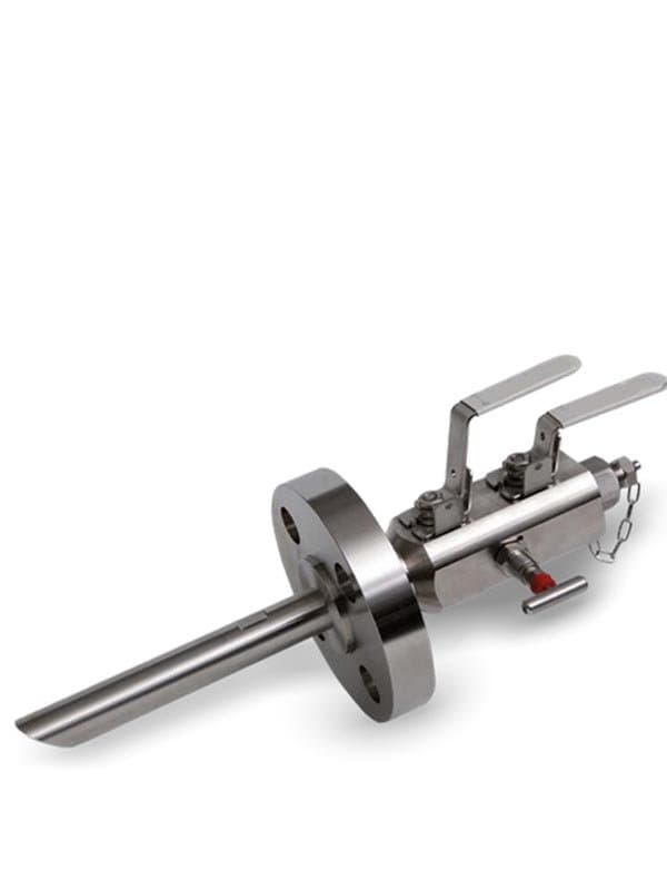
取样DBB针阀
快速规格 1/4" - 1/2"(DN8 - DN15) 高达10,000 psi / Class 150 - 2500等效 API 6D、ISO 15848、NACE MR0175(含硫工况配置) A182 F316、A182 F51、A182 F53、Monel(NACE含硫工况) PTFE、PEEK、金属对金属(Stellite 6) 带DBB隔离的采样针阀、紧凑阀体、螺纹连接(NPT/BSP)、带双重阻断保护的采样口 从在线工艺管线采样——以及为什么采样管嘴需要DBB保护 采样阀从在线管道中提取少量工艺流体,用于实验室分析、质量验证或法规合规测试——样品必须具有代表性(与主工艺流相同的成分、相同的压力、相同的温度),且提取必须安全(抽取样品的技术人员不应暴露于全管线压力下,管道也不应通过采样管嘴失去密封性)。简单的单阻断采样阀提供一个隔离边界——当阀门关闭时,采样口与管道隔离。但该隔离是单点的:如果单个阀座泄漏,管线压力同时到达采样口和样品容器——技术人员在处理本应处于大气压力的样品瓶时会被活体工艺压力击中。在碳氢化合物、化学品和酸性气体采样应用中,当工艺介质为易燃、有毒或高压时,这种单点隔离失效就是安全事故——而不仅仅是样品污染问题。 FLOWKS采样用DBB针阀在采样连接点提供双阻塞与排放隔离——两个独立的针阀阻塞阀座,中间设有排放腔,紧凑型阀体可直接安装于管道采样接口处。上游针阀将管道压力与排放腔隔离。下游针阀阻止任何通过上游针阀泄漏的压力到达采样口。两个针阀之间的排放腔通向大气或密闭排放系统——排放口压力为零确认两个阻塞针阀均密封良好,之后方可打开采样口进行样品提取。DBB结构在采样接口处提供与仪表及变送器隔离点相同的已验证隔离逻辑:在打开下游侧通向大气之前,通过排放口确认隔离状态。在工艺采样中,这一验证步骤至关重要,因为技术人员即将打开一个设计用于常压的采样容器——在未确认隔离完好之前,不能让常压采样瓶接触哪怕微量的管道活压。 针型阀芯——适用于小口径样品提取的正确密封机构 样品提取量很小——几毫升到几百毫升,通过1/4英寸或1/2英寸孔径的采样口抽取。孔径小是因为样品量小且提取速率需要精确控制(快速抽取会引入非代表性流体;缓慢、受控的抽取可获得代表性组分)。1/4英寸至1/2英寸孔径的针型阀芯提供采样所需的流量控制精度——锥形针塞随阀杆旋转逐步调节流通面积,使技术人员能够精细控制提取速率,而非简单的开/关二元操作。这种调节能力内置于针型几何结构中——针阀不仅开启和关闭,还能在部分开启位置进行节流,此时针尖与阀座锥面之间的流通面积由阀杆旋转角度精确控制。 对于DBB堵塞阀座(上游和下游),相同的针头几何形状可实现渐进式楔入密封——通过增加阀杆扭矩实现更紧密的关闭,与法兰螺纹式针头DBB相同。对于取样提取口(下游连接点,用于连接样品容器),针头的节流功能可实现对提取速率的精确控制——技术人员不会完全打开取样口,让工艺介质以管道流速涌入容器。相反,针头会逐步打开,样品以可控速率流动,容器缓慢而稳定地填充,并且由于提取速率不会在样品流中产生湍流或优先相分离,因此样品成分保持代表性。 样品提取程序——打开通向大气前的DBB验证 使用DBB针阀的采样程序遵循一个明确的顺序,三阀杆结构在物理上强制执行该顺序: 关闭两个关断针阀(上游和下游)——采样口与管道完全隔离。 打开排放针阀——排放两个关断针阀之间腔体内的任何残余压力。检查排放处是否为零压力。零压力确认两个关断针阀均保持密封。 如果排放显示零压力:继续进行样品提取。将采样容器连接到采样口接口。逐步打开下游(仪表侧)关断针阀——受控流入采样容器。收集到所需样品量后关闭下游针阀。关闭排放针阀。采样容器处于大气压力并含有代表性工艺样品。 若排放口显示活压:不得继续操作。上游阻塞针阀存在泄漏——隔离已失效。排放口在采样口打开之前已揭示故障。停止操作并报告,在尝试样品提取之前更换或修复上游阀座。 该顺序不可跳过——三个独立手柄在物理上分隔每个步骤,关断与提取之间的排放验证强制技术人员在将采样容器暴露于任何潜在工艺压力之前确认隔离状态。对于有毒和易燃介质采样,该顺序是安全规程——不是建议,不是最佳实践,而是监管框架和公司安全标准对从活管道进行工艺采样所强制要求的规定程序。 NACE MR0175酸性工况——从含H₂S工艺流中采样 含硫天然气和含硫原油取样(含有H₂S浓度高于NACE MR0175阈值的工艺流)需要使用能够抵抗硫化物应力开裂的材料——硫化氢环境会在应力集中和微观结构敏感性重合的点(螺纹根部、阀座接触区、阀杆贯穿阀体的穿透点)侵蚀标准不锈钢。FLOWKS取样用DBB针阀提供符合NACE MR0175的配置——阀体材料根据工艺流的具体H₂S浓度、pH值和温度条件按NACE要求指定(Monel用于严苛含硫工况,Inconel用于高温含硫工况,符合NACE的F316用于标准合金满足硬度和热处理要求的温和含硫条件)。阀座和阀内件材料也按NACE指定——针尖和阀座锥面上的Stellite 6堆焊符合NACE要求,并提供含硫工况所需的金属对金属密封耐久性(PTFE和PEEK在化学上与H₂S相容,但金属阀座更受青睐,因为取样阀在反复循环操作下需要机械耐久性)。 酸性工况下的取样本质上比非酸性工况下的取样更危险——硫化氢的暴露阈值很低(8 小时暴露 10 ppm,15 分钟暴露 100 ppm,300 ppm 为立即威胁生命或健康的浓度),而且取样操作会使技术人员非常靠近取样口,任何泄漏或隔离失效都会直接导致他们暴露于工艺流体中。在酸性工况下,DBB 验证步骤(打开取样口前的排气检查)更为关键——隔离失效的后果不仅仅是样品污染,而是急性中毒暴露。符合 NACE 标准的材料和 DBB 隔离结构相结合,使酸性工况下的取样安全性达到了阀门设计所能达到的极限——但操作规程的严格性(遵循操作顺序、排气验证、不走捷径)是阀门设计能够支持但无法取代的人为因素。 应用场景和下游连接。仪表块DBB:仪表隔离——下游连接接至永久安装在阀门上的仪表或变送器。取样DBB:样品提取——下游连接是取样口,技术人员在此连接临时样品容器进行提取,样品收集后将其移除。相同的DBB隔离架构(两个截止阀座+泄放腔),但下游侧功能不同——仪表块为永久仪表连接,取样阀为临时样品提取口。 节流能力和孔径。取样需要受控的提取速率——样品缓慢而稳定地流入容器,而非管道流速。针形阀内件在部分开度下节流,使技术人员能够精细控制提取速率。球阀内件是开关式——开启时全流量,关闭时无流量,中间无调节。在取样操作的1/4"-1/2"孔径范围内,针形阀内件在高压力下也比球阀内件提供更好的关断性能——渐进楔形密封保持紧密关闭,而微孔尺寸下的球阀座在机械上处于临界状态。 阀体、阀内件和阀座材料按规格要求抵抗含H₂S环境中的硫化物应力开裂。Monel阀体用于严苛含硫工况。符合NACE的热处理F316用于温和含硫条件。Stellite 6阀内件用于金属对金属密封,符合NACE要求并在反复循环下保持耐久性。NACE合规在含硫工况中不是可选项——它是防止H₂S环境中灾难性失效(硫化物应力开裂)的材料规格要求。 关闭两个阻断针阀,打开泄压针阀,检查泄压口是否为零压力。零压确认两个针阀均保持密封——可安全进行样品提取。泄压口有活压则表明上游针阀失效——不要继续,不要打开取样口,不要让样品容器承受工艺压力。泄压检查只需几秒钟,它是隔离验证与样品提取之间的安全闸门。 是的——采用合适的阀体和阀芯材料(低温环境下使用A182、F316L或Inconel合金),以及加长的阀盖设计,使阀杆填料远离低温阀体。液化天然气取样、液氮取样和其他低温工艺流程需要特定的材料规格和阀盖结构,以确保在低至-196°C的温度下仍能保持机械性能和填料功能。DBB隔离结构和针阀阀芯节流功能在低温环境下,通过适当的材料和设计改进即可实现。
技术概述
双关断与排放阀提供两个独立的密封边界,并在两者之间设有可验证的排放腔。这听起来有些多余,直到你站在一条1500 psi碳氢化合物管线的压力表旁,看着单个隔离阀座向仪表连接处渗漏工艺介质。一个阀座可能泄漏。一个阀座可能失效。DBB通过要求上游和下游阀座同时密封来消除这一风险,两者之间的排放腔通向大气或封闭排放口,这样你可以在打开仪表侧之前目视确认两个阀座均已密封。FLOWKS生产仪表阀组、法兰式、耳轴式和针阀式DBB配置——从紧凑型1/2英寸仪表隔离阀到全通径管道DBB单元。仪表阀组DBB直接安装在仪表接口处,采用无法兰或法兰连接。法兰式和耳轴式DBB用于隔离管线段以进行维护、检查和压力验证。采样针阀式DBB在两个阻断阀座之间增加一个采样口,允许在不破坏隔离的情况下提取流体。每种DBB配置都遵循相同的功能原理:两个阀座、一个排放口,在继续操作前验证两个边界均保持零压力。
FLOWKS双关断与排放(DBB)阀提供经过验证的双重隔离,在两个独立密封边界之间设有通风腔。上游阀座阻断工艺压力;下游阀座保护仪表或下游管线;两者之间的排放腔通向大气或封闭排放口,在任何下游作业开始前目视确认两个阀座均处于密封状态。仪表阀组无法兰DBB阀直接旋入仪表接口——1/2英寸至2英寸,Class 150–1500,无需法兰螺栓或垫片对中即可紧凑安装。仪表阀组SBB(单关断与排放)阀提供一个阻断阀座加一个排放口,适用于不要求双重隔离的应用。法兰式DBB阀通过螺栓连接至管道法兰接口,用于较大直径的隔离。耳轴式DBB阀将双关断与排放功能集成到耳轴安装的球阀阀体中,适用于全通径管道工况。法兰对螺纹针阀式DBB阀将法兰工艺连接与螺纹仪表连接相结合,在管道标准之间架起桥梁。采样针阀式DBB阀在排放腔内增加一个采样提取口,允许在不破坏任一隔离边界的情况下收集流体。FLOWKS DBB阀满足API 6D对双重隔离的要求,并可提供ISO 15848逸散性排放认证。阀座选项包括PTFE、PEEK和金属对金属(Stellite 6),以适应化学兼容性和温度范围匹配。
产品下载
使用该产品的行业
各工业领域的应用
Oil & Gas
Upstream, midstream and downstream valve solutions meeting API 6D, API 607 fire-safe requirements. From wellhead to refinery, FLOWKS provides reliable valve solutions for the most demanding oil and gas applications.
LNG
Cryogenic valves engineered for liquefied natural gas processing and transportation. FLOWKS cryogenic service valves are tested to -196degC per BS 6364.
Refining
Heavy-duty valves designed for the extreme conditions of petroleum refining. FLOWKS valves handle high temperatures, corrosive media, and erosive service in refineries globally.
products.lookingMore
products.lookingMoreDesc
Ball Valves
FLOWKS offers floating ball valve, trunnion mounted ball valve and top entry ball valve for oil & gas, petrochemical and power generation. Designed per API 6D, API 608 and ASME B16.34.
Gate Valves
FLOWKS gate valves for isolation service in piping systems. Flexible wedge, solid wedge, slab and expanding gate designs per API 600, API 602 and ASME B16.34.
Globe Valves
FLOWKS globe valves for throttling and isolation. Standard, angle, Y-pattern and bellows seal configurations per API 602 and BS 1868.
Check Valves
FLOWKS check valves prevent reverse flow. Dual plate, swing, tilting disc and lift check designs per API 594 and BS 1868.