products.productRange
Rangkaian lengkap katup industri untuk setiap aplikasi.
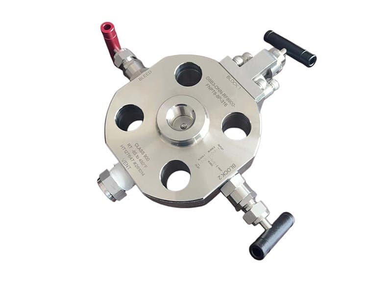
DBB Gauge Block-NonoFlange
1/2" - 2" (DN15 - DN50) Kelas 150 - 1500 / hingga 10.000 psi (konfigurasi tipe jarum) API 6D, API 607, ASME B16.34, ISO 15848 A182 F316, A182 F51, A182 F53 PTFE, PEEK, metal-to-metal (Stellite 6) Badan blok pengukur dengan koneksi non-flange (tanpa flensa), double block & bleed dengan port bleed tunggal, katup instrumentasi kompak Apa yang Dilakukan Gauge Block DBB——dan Mengapa Insinyur Instrumen Menspesifikasikannya Pengukur tekanan, pemancar, dan titik sadap instrumen memerlukan isolasi untuk kalibrasi, penggantian, dan verifikasi tanpa mematikan jalur proses utama. Isolasi itu harus ganda——satu dudukan pemblokiran tidak cukup ketika jalur proses membawa 1500 psi hidrokarbon atau 10.000 psi fluida hidrolik. Satu dudukan bisa bocor. Satu dudukan bisa gagal. Dan jika itu terjadi, media proses mencapai instrumen dan port ventilasi secara bersamaan——teknisi terkena tekanan proses langsung saat mencoba memverifikasi nol. Itulah sebabnya definisi API 6D tentang Double Block and Bleed mensyaratkan dua batas penyegelan independen dengan rongga ventilasi di antara keduanya: dudukan pertama memblokir tekanan hulu, dudukan kedua memblokir tekanan hilir menuju instrumen, dan rongga ventilasi di antara kedua dudukan memberi Anda zona tekanan-nol terverifikasi di mana Anda dapat mengonfirmasi bahwa kedua dudukan menahan sebelum membuka sisi instrumen. Katup DBB gauge block menempatkan kedua dudukan pemblokiran dan rongga ventilasi ke dalam satu badan kompak yang dipasang langsung di titik koneksi instrumen——tanpa katup terpisah, tanpa rakitan fitting-T, tanpa banyak jalur kebocoran potensial antara fungsi pemblokiran dan ventilasi. Nonoflange——Tanpa Flensa, Tanpa Baut, Pemasangan Ulir Langsung Koneksi nonoflange berarti badan katup disekrup langsung ke titik koneksi instrumen——biasanya sadap berulir NPT 1/2" atau 3/4" pada dinding pipa atau bejana——tanpa baut flange antara katup dan proses. Pemasangan langsung dengan ulir itu menghilangkan gasket flange sebagai jalur kebocoran potensial (flange bocor di gasket; koneksi berulir tidak memiliki gasket), mengurangi ruang pemasangan (tanpa lingkaran baut flange, tanpa penyelarasan gasket, tanpa prosedur pengencangan baut——cukup sekrup katup ke sadap dan kencangkan dengan kunci), dan menjaga tinggi rakitan keseluruhan ke dimensi minimum praktis untuk pemasangan instrumen. Gauge block DBB berflensa ada (FLOWKS juga memproduksinya——lihat seri Flange DBB), dan melayani aplikasi di mana titik koneksi instrumen berflensa daripada berulir. Tetapi untuk mayoritas titik sadap instrumen pada pipa proses——yang merupakan boss pipa berulir NPT dilas ke jalur utama——versi nonoflange adalah opsi pemasangan yang lebih sederhana, lebih kompak, dan lebih langsung. Tanpa flange untuk dibaut. Tanpa gasket untuk diselaraskan. Tanpa prosedur baut flange untuk dieksekusi. Sekrup langsung. Kencangkan dengan kunci. Selesai. Geometri bodi yang ringkas merupakan persyaratan fungsional, bukan preferensi kosmetik. Instalasi instrumen memiliki ruang fisik yang terbatas——pengukur atau transmitter duduk di ujung katup, dan keduanya harus muat di dalam rak pipa atau envelope jarak bebas skirt bejana. Bodi blok pengukur dengan ulir nonoflange menjaga panjang total rakitan (koneksi proses ke flange atau ulir instrumen) pada dimensi minimum yang masih menampung kedua dudukan penutup dan rongga bleed. Panjang rakitan yang lebih pendek berarti tonjolan yang lebih sedikit dari dinding pipa, kerentanan yang lebih rendah terhadap kerusakan benturan dari aktivitas pemeliharaan di area rak pipa yang padat, dan bobot yang lebih ringan pada boss pipa berulir (koneksi berulir menahan beban lentur dari bobot rakitan——lebih pendek dan lebih ringan berarti tegangan lentur yang lebih rendah pada pengikatan ulir). Dua Dudukan dan Satu Bleed——Arsitektur Fungsional Isolasi DBB Bodi blok pengukur berisi dua elemen dudukan independen yang disusun secara seri di sepanjang jalur aliran——dudukan hulu (sisi proses) dan dudukan hilir (sisi instrumen). Setiap dudukan menutup secara independen: dudukan hulu memblokir tekanan proses agar tidak masuk ke rongga bleed di antara kedua dudukan, dan dudukan hilir memblokir tekanan apa pun yang mungkin bocor melewati dudukan hulu agar tidak mencapai koneksi instrumen. Port bleed terletak di antara kedua dudukan——port berdiameter kecil (biasanya 1/4" NPT) yang membuang rongga ke atmosfer atau ke sistem drainase tertutup. Dalam operasi: kedua dudukan tertutup, katup bleed terbuka——port bleed memverifikasi tekanan nol di rongga antara dudukan, mengonfirmasi bahwa kedua batas penutup menahan. Jika dudukan hulu bocor, tekanan proses masuk ke rongga dan dibuang melalui port bleed——teknisi melihat tekanan hidup di bleed dan mengetahui dudukan hulu tidak menahan. Jika dudukan hilir bocor, tekanan dari rongga (jika ada) mencapai sisi instrumen——teknisi melihat tekanan di koneksi instrumen dan...
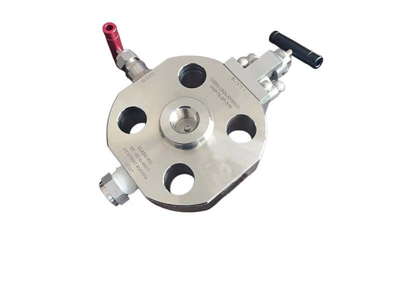
SBB Gauge Block NonoFlange
1/2" - 2" (DN15 - DN50) Kelas 150 - 1500 / hingga 10.000 psi (konfigurasi tipe jarum) API 6D, API 607, ASME B16.34, ISO 15848 A182 F316, A182 F51, A182 F53 PTFE, PEEK, logam-ke-logam (Stellite 6) Badan gauge block dengan sambungan nonoflange, blok tunggal & bleed dengan port verifikasi bleed, katup instrumen kompak SBB vs DBB—Satu Dudukan atau Dua, dan Kapan Satu Sudah Cukup Double Block and Bleed (DBB) menyediakan dua batas penyegelan independen dengan rongga bertekanan nol yang terverifikasi di antara keduanya—jaminan isolasi maksimum yang tersedia dalam satu badan katup. Tetapi tidak setiap aplikasi isolasi instrumen membutuhkan jaminan maksimum. Beberapa aplikasi membutuhkan isolasi terverifikasi dengan pemeriksaan bleed, tetapi kondisi proses tidak menuntut dua batas pemblokiran independen: jalur utilitas bertekanan rendah, media tidak berbahaya (air, udara, nitrogen), keran instrumen pada layanan tidak mudah terbakar di mana konsekuensi kebocoran satu dudukan adalah kesalahan pembacaan gauge, bukan insiden keselamatan. Untuk aplikasi tersebut, Single Block and Bleed (SBB) menyediakan satu dudukan pemblokiran dan satu port verifikasi bleed—cukup isolasi untuk melepas instrumen dengan aman (dudukan memblokir tekanan proses, port bleed memverifikasi dudukan menahan sebelum sisi instrumen dibuka), tetapi hanya dengan satu batas penyegelan, bukan dua. Trade-off-nya sederhana: satu dudukan alih-alih dua berarti lebih sedikit komponen, panjang rakitan lebih pendek, biaya lebih rendah, dan operasi lebih sederhana—tetapi hanya satu batas pemblokiran, bukan dua yang independen. Jika dudukan tunggal itu gagal, tidak ada dudukan cadangan untuk mempertahankan isolasi. Port bleed mengungkapkan kegagalan (tekanan proses muncul di bleed), tetapi isolasi hilang sampai dudukan diperbaiki. Katup gauge block SBB FLOWKS menggunakan geometri badan kompak yang sama dengan versi DBB—pemasangan ulir nonoflange, sambungan NPT langsung ke keran instrumen, tinggi rakitan minimum—tetapi dengan satu dudukan pemblokiran alih-alih dua. Port bleed terletak di sisi hilir dudukan pemblokiran tunggal, menyediakan fungsi verifikasi yang membedakan SBB dari isolasi blok tunggal sederhana tanpa kemampuan bleed. Dengan dudukan pemblokiran tertutup dan katup bleed terbuka, tekanan nol di port bleed mengonfirmasi dudukan tunggal menahan. Jika tekanan proses muncul di bleed, dudukan telah gagal—isolasi terganggu dan sisi instrumen terpapar tekanan proses langsung. Kemampuan verifikasi itu (pemeriksaan bleed sebelum membuka sisi instrumen) adalah yang membuat SBB menjadi metode isolasi yang lebih aman daripada katup blok tunggal sederhana tanpa bleed—teknisi tidak mengasumsikan dudukan menahan, teknisi memverifikasinya melalui port bleed. Tetapi tetap hanya satu dudukan—jika verifikasi mengungkapkan kegagalan, tidak ada cadangan. Kapan SBB Adalah Spesifikasi yang Tepat—dan Kapan Tidak Keputusan antara SBB dan DBB bukan tentang preferensi atau optimasi biaya—ini tentang analisis konsekuensi. Apa yang terjadi jika dudukan pemblokiran tunggal bocor atau gagal? Jika konsekuensinya adalah kesalahan pembacaan gauge atau penyimpangan kalibrasi transmitter pada jalur utilitas tidak berbahaya—SBB sudah memadai. Port bleed mengungkapkan kegagalan, pemeliharaan mengganti dudukan, dan proses berlanjut. Jika konsekuensinya adalah paparan media beracun, mudah terbakar, atau bertekanan tinggi yang akan menciptakan insiden keselamatan atau pelepasan lingkungan—DBB wajib. Dudukan tunggal di SBB menyediakan isolasi terverifikasi saat menahan, tetapi tidak menyediakan cadangan saat gagal. Pada layanan berbahaya, itu tidak dapat diterima—dudukan kedua di DBB menyediakan cadangan yang mempertahankan isolasi bahkan ketika dudukan pertama gagal, dan rongga bleed mengungkapkan dudukan mana yang gagal tanpa kehilangan kemampuan isolasi keseluruhan. Kerangka kerja regulasi dan standar industri semakin default ke DBB untuk isolasi proses pada pipa hidrokarbon, kimia, dan bertekanan tinggi—definisi API 6D tentang Double Block and Bleed adalah spesifikasi dasar untuk instalasi baru pada layanan mudah terbakar dan beracun. SBB tetap sesuai untuk layanan utilitas tidak berbahaya (udara instrumen, blanketing nitrogen, air bertekanan rendah, sistem HVAC) di mana konsekuensi isolasi adalah ketidaknyamanan operasional, bukan risiko keselamatan. Pada aplikasi tersebut, arsitektur SBB yang lebih sederhana (satu dudukan, satu bleed, lebih sedikit komponen, rakitan lebih pendek) menyediakan isolasi terverifikasi dengan margin keselamatan yang memadai—pengurangan biaya dan kompleksitas dengan menghilangkan dudukan kedua dibenarkan oleh konsekuensi yang lebih rendah dari kegagalan satu dudukan. Port Bleed—Fungsi Verifikasi yang Sama, Diposisikan Setelah Satu Dudukan Alih-alih Dua Pada katup DBB, port pembuangan terletak di antara dua dudukan penutup——katup ini membuang tekanan...
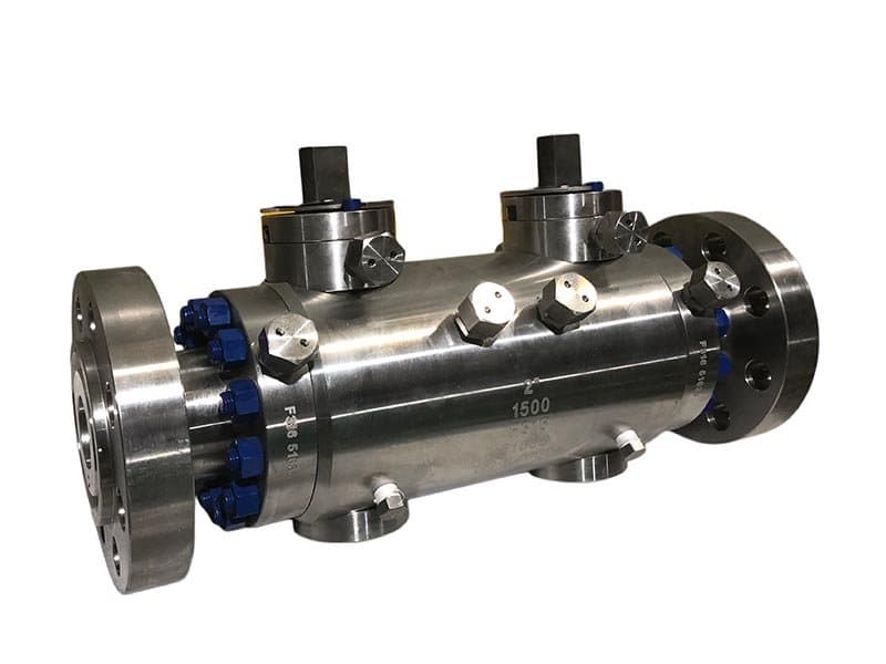
DBB Trunnion Double Block & Bleed
Tentang Trunnion Double Block & Bleed DBB 2" - 24" (DN50 - DN600) API 6D, API 607, ASME B16.34, ISO 15848 A216 WCB, A351 CF8M, A182 F51, A182 F53 PTFE, Nylon, PEEK, logam-ke-logam (Stellite 6) Bola terpasang trunnion dengan dudukan pegas, double block & bleed dalam satu badan, akses perawatan sisi-masuk atau atas-masuk Isolasi Pipa yang Tidak Mempercayai Satu Dudukan——Karena Konsekuensi Pipa Tidak Mengizinkannya Katup isolasi pipa terletak di antara bagian-bagian pipa proses yang membawa hidrokarbon, bahan kimia, atau gas bertekanan tinggi——media di mana konsekuensi kegagalan isolasi bukanlah kesalahan pembacaan gauge, melainkan insiden keselamatan, pelepasan lingkungan, atau pelanggaran regulasi. Pada aplikasi tersebut, satu dudukan penutup tidak cukup meskipun sedang menahan——karena konsekuensi dari kegagalan satu dudukan itu tidak dapat diterima. Katup blok tunggal menyediakan isolasi dari satu batas penyegelan; jika batas itu bocor, media mencapai bagian hilir yang seharusnya diisolasi. Katup trunnion DBB menyediakan isolasi dari dua batas penyegelan independen dengan rongga bertekanan nol yang terverifikasi di antara keduanya——dudukan hulu menahan tekanan dari bagian pipa aktif, dudukan hilir menahan tekanan menuju bagian yang diisolasi, dan rongga pembuangan di antara kedua dudukan memberi Anda zona bertekanan nol terverifikasi yang mengonfirmasi kedua dudukan menahan sebelum bagian hilir dibuka untuk perawatan, inspeksi, atau operasi hot-tap. Dua dudukan independen, dua mode kegagalan independen, satu status isolasi terverifikasi yang terlihat melalui port pembuangan. Arsitektur bola terpasang trunnion menyediakan platform struktural untuk dua dudukan pegas independen dalam satu badan katup. Bola ditambatkan oleh pin trunnion atas dan bawah——bola tidak mengapung di bawah perbedaan tekanan seperti katup bola mengambang. Dua cincin dudukan berada di sisi berlawanan dari bola, masing-masing didorong pegas secara independen terhadap permukaan bola. Ketika bola berputar ke posisi tertutup, kedua dudukan menutup secara bersamaan——dudukan hulu terhadap tekanan hulu, dudukan hilir terhadap tekanan hilir, keduanya independen, keduanya dapat diverifikasi melalui rongga pembuangan. Arsitektur trunnion itulah yang membuat DBB layak pada ukuran lubang yang lebih besar——katup bola mengambang memiliki satu arah penyegelan (bola mendorong dudukan hilir di bawah tekanan hulu), tetapi katup trunnion memiliki dua arah penyegelan independen (setiap dudukan pegas mendorong bola dari sisinya sendiri). Dua dudukan. Dua pegas. Dua gaya penyegelan independen. Satu rongga isolasi terverifikasi di antara keduanya. Mengapa Trunnion DBB Menggantikan Rakitan Tiga Katup Lama Sebelum katup DBB badan tunggal menjadi spesifikasi standar isolasi pipa, industri menggunakan tiga katup terpisah untuk mencapai double block and bleed: dua katup isolasi (satu hulu, satu hilir) dan satu katup pembuangan dalam fitting tee di antara keduanya. Rakitan tiga katup itu berfungsi——menyediakan dua batas blok dan satu port verifikasi pembuangan——tetapi memiliki empat masalah bawaan yang dihilangkan oleh trunnion DBB badan tunggal. Pertama: banyak jalur kebocoran potensial. Tiga katup berarti tiga badan katup, tiga set koneksi badan-ke-pipa, tiga gasket bonnet-ke-badan, dan koneksi fitting tee di antara ketiga katup——setiap koneksi adalah jalur kebocoran eksternal potensial. DBB badan tunggal menghilangkan semua koneksi antar-katup——kedua dudukan blok dan port pembuangan berada di dalam satu badan, tanpa koneksi eksternal antara fungsi blok dan pembuangan kecuali satu port pembuangan ke atmosfer atau drain. Lebih sedikit koneksi eksternal berarti lebih sedikit jalur kebocoran potensial. Kedua: ruang pemasangan yang lebih besar. Tiga katup terpisah dengan fitting tee menempati ruang rak pipa yang jauh lebih banyak daripada DBB badan tunggal——panjang rakitan tiga katup adalah gabungan panjang dua katup isolasi ditambah fitting tee, sementara DBB badan tunggal muat dalam panjang satu badan katup. Pada instalasi rak pipa yang padat di mana alokasi ruang menjadi kendala, jejak kompak DBB badan tunggal adalah keunggulan praktis yang melampaui estetika. Ketiga: berat total yang lebih tinggi. Tiga badan katup ditambah fitting tee lebih berat daripada satu badan DBB——lebih banyak baja di rak pipa, lebih banyak berat pada penyangga pipa, lebih banyak beban struktural. Pengurangan berat bukan sekadar kenyamanan——pada instalasi pipa lubang besar, perbedaan berat antara rakitan tiga katup dan DBB badan tunggal dapat memengaruhi desain penyangga pipa dan perhitungan analisis tegangan. Keempat: kompleksitas operasi berurutan. Mengoperasikan tiga katup terpisah memerlukan urutan tertentu: tutup katup isolasi hulu, buka katup pembuangan, verifikasi tekanan nol di pembuangan, tutup katup isolasi hilir, lalu lanjutkan pekerjaan hilir. Urutan itu harus...
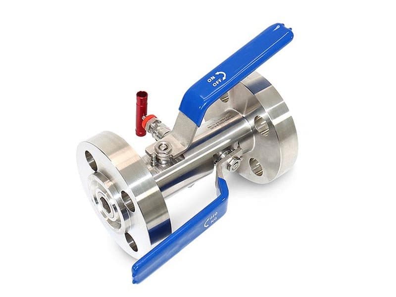
DBB Block-Bleed Flange
Tentang Flensa Blok-Bleed DBB Spesifikasi Singkat 2" - 20" (DN50 - DN500) Kelas 150 - 600 API 6D, API 607, ASME B16.34, ISO 15848 A216 WCB, A351 CF8M, A182 F51 PTFE, Nilon, PEEK, logam-ke-logam (Stellite 6) Koneksi ujung berflensa (RF/RTJ), bonnet baut, blok ganda & bleed dalam satu badan, operasi manual atau aktuator Koneksi Berflensa——Di Mana Spesifikasi Pipa Mensyaratkan Koneksi Ujung Baut Katup DBB berflensa memiliki fungsi isolasi yang sama dengan DBB trunnion——dua dudukan pemblokiran independen dengan rongga pembuangan terverifikasi di antara keduanya——tetapi dengan koneksi ujung berflensa ke pipa, bukan las pantat. Koneksi berflensa (permukaan timbul atau sambungan cincin sesuai ASME B16.5) adalah metode koneksi pipa standar untuk Kelas 150 hingga Kelas 600 di banyak spesifikasi fasilitas——khususnya pada sistem pipa proses di mana aksesibilitas perawatan mensyaratkan koneksi baut yang dapat dibongkar tanpa memotong dan mengelas ulang pipa. Katup DBB las pantat (seperti seri DBB las penuh FLOWKS) secara permanen menyambungkan katup ke pipa——pelepasan memerlukan pemotongan las dan pengelasan ulang pengganti. Katup DBB berflensa dibuka bautnya dari flensa pipa——empat baut per flensa (pada ukuran lebih kecil) atau puluhan pada ukuran lebih besar, tetapi prinsipnya sama: buka baut, lepaskan, ganti, pasang baut kembali. Tanpa pengelasan. Tanpa izin kerja panas. Tanpa inspeksi radiografi las pengganti. Aksesibilitas koneksi baut itu adalah alasan utama fasilitas menspesifikasikan katup DBB berflensa pada pipa Kelas 150-600——logistik perawatan koneksi baut lebih sederhana, lebih cepat, dan lebih murah daripada koneksi las pada kelas tekanan di mana sambungan flensa memadai secara struktural. Di atas Kelas 600, koneksi las pantat menjadi spesifikasi standar karena sambungan flensa pada Kelas 900 ke atas memerlukan baut yang lebih berat, permukaan gasket yang lebih besar, dan beban tegangan baut yang lebih tinggi yang mendorong kompleksitas perawatan koneksi flensa melampaui batas praktis untuk banyak instalasi. DBB berflensa FLOWKS mencakup Kelas 150 hingga Kelas 600——rentang tekanan di mana koneksi flensa melayani mayoritas instalasi pipa proses dan di mana keunggulan perawatan koneksi baut paling bernilai. Bonnet Baut——Akses Perawatan Tanpa Melepas Katup dari Pipa Bonnet (bagian badan katup yang berisi batang, packing, dan bantalan trunnion atas) terhubung ke badan melalui sambungan bonnet-ke-badan yang dibaut—dibaut, bukan dilas. Desain bonnet yang dibaut ini menyediakan akses perawatan ke packing batang, bantalan trunnion atas, dan rakitan bola-dan-dudukan tanpa melepas seluruh katup dari flange pipa. Prosedur perawatan: buka baut bonnet, angkat rakitan bonnet (batang, pin atas bola, packing) keluar dari badan, akses cincin dudukan dan bola untuk inspeksi atau penggantian, pasang kembali bonnet dengan gasket baru, kencangkan baut, terapkan torsi ulang. Flange pipa tetap terpasang—badan katup tetap terhubung ke pipa selama operasi perawatan berlangsung. Kemampuan perawatan inline ini adalah prinsip yang sama yang digunakan katup bola top-entry FLOWKS untuk layanan pipa terkubur dan las—perbedaannya adalah bahwa bonnet yang dibaut pada DBB berflange melayani instalasi sambungan berflange di mana flange pipa itu sendiri adalah titik pembongkaran utama, dan baut bonnet adalah titik akses sekunder untuk perawatan trim internal. Gasket bonnet-ke-badan adalah elemen penyegel yang kritis—ini adalah batas tekanan antara rongga badan (terpapar tekanan pipa) dan rongga bonnet (terpapar packing dan batang). Spesifikasi gasket disesuaikan dengan media proses dan kondisi suhu: gasket spiral-wound (lilitan stainless dengan isian grafit atau PTFE) untuk layanan proses umum, gasket cincin logam untuk aplikasi suhu tinggi dan fire-safe di mana gasket spiral-wound akan terdegradasi di bawah beban termal berkelanjutan. Gasket diganti setiap kali bonnet dibuka bautnya—gasket adalah elemen penyegel sekali pakai, tidak dapat digunakan ulang. Persyaratan penggantian ini adalah praktik perawatan standar di seluruh desain katup bonnet-baut—Anda tidak menggunakan ulang gasket pada batas tekanan, Anda memasang yang baru setiap kali sambungan dirakit ulang. Double Block and Bleed—Arsitektur Fungsional yang Sama, Paket Instalasi Berflange Arsitektur isolasi DBB di dalam badan berflange identik dengan trunnion DBB: dua dudukan pegas independen yang menekan bola yang dipasang di trunnion dari sisi yang berlawanan, dengan rongga bleed di antara keduanya yang mengalirkan keluar melalui port yang ditentukan pada badan. Dudukan hulu memblokir tekanan proses dari bagian pipa aktif. Dudukan hilir memblokir tekanan menuju bagian yang diisolasi. Rongga bleed memverifikasi kedua dudukan secara bersamaan—tekanan nol di bleed mengonfirmasi kedua batas pemblokiran menahan. Perilaku fungsionalnya sama terlepas dari jenis sambungan (berflange...
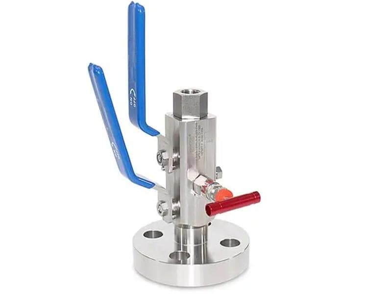
DBB Needle Type Flange to Screw
Spesifikasi Singkat 1/2" - 1" (DN15 - DN25) hingga 10.000 psi (Setara Kelas 150 - 2500) API 6D, API 607, ASME B16.34, ISO 15848 A182 F316, A182 F51, A182 F53 PTFE, PEEK, logam-ke-logam (Stellite 6) Sambungan sisi proses bergelang + sambungan sisi instrumen berulir (NPT), tipe jarum DBB dengan bodi ringkas, double block & bleed dengan satu port bleed Flange di Satu Ujung, Sekrup di Ujung Lainnya——Saat Pipa Menggunakan Flange tetapi Instrumen Menggunakan Ulir Pipa proses pada titik sambungan instrumen sering kali memiliki katup isolasi bergelang di sisi pipa dan sambungan berulir (NPT) di sisi pengukur atau transmitter——spesifikasi pipa mensyaratkan sambungan bergelang di atas bukaan 1" untuk integritas struktural dan aksesibilitas perawatan, tetapi sambungan instrumen (pengukur, transmitter, sakelar tekanan) hampir selalu berulir 1/2" NPT karena instrumen tidak memiliki sambungan proses bergelang. Ketidakcocokan itu——bergelang di satu sisi, berulir di sisi lain——persis itulah yang diatasi oleh katup ini. Sambungan sisi proses (hulu) adalah ujung bergelang (RF atau RTJ sesuai ASME B16.5) yang dibaut langsung ke flange pipa. Sambungan sisi instrumen (hilir) adalah port NPT berulir tempat pengukur atau transmitter dipasang langsung. Dua dudukan penutup dan rongga bleed berada di antara sambungan hulu bergelang dan sambungan hilir berulir——fungsi isolasi DBB mencakup seluruh jalur aliran dari antarmuka pipa bergelang hingga antarmuka instrumen berulir, tanpa fitting tambahan, adaptor, atau jalur kebocoran antar-sambungan di antara keduanya. Tanpa konfigurasi flensa-ke-sekrup ini, pemasang harus merakit katup isolasi flensa, fitting pereduksi (adaptor flensa-ke-ulir), dan katup pembuangan terpisah—tiga komponen dengan dua titik interkoneksi (flensa-ke-adaptor, adaptor-ke-instrumen) yang keduanya berpotensi menjadi jalur kebocoran eksternal. Setiap interkoneksi menambahkan gasket atau segel ulir yang harus dipelihara secara independen. Katup tipe jarum flensa-ke-sekrup DBB menghilangkan kedua titik interkoneksi—ujung flensa langsung terpasang ke pipa, ujung berulir langsung menerima instrumen, dan isolasi DBB berada di dalam satu badan di antara keduanya. Tanpa adaptor. Tanpa fitting tambahan. Tanpa jalur kebocoran interkoneksi. Satu badan katup mencakup seluruh ketidaksesuaian sambungan. Tipe Jarum——Bodi Ringkas untuk Titik Instrumentasi Tekanan Tinggi Penunjukan tipe jarum berarti dudukan penutupnya adalah trim katup jarum, bukan trim katup bola——plug jarum meruncing yang duduk di dalam ring dudukan berbentuk kerucut yang sesuai, bukan bola berputar yang menyegel terhadap ring dudukan datar atau berkontur. Trim jarum memiliki dua keunggulan praktis pada ukuran bukaan kecil dan tekanan tinggi: Pertama: geometri dudukan jarum-dan-kerucut menyegel secara progresif——jarum duduk lebih dalam ke kerucut seiring meningkatnya gaya penutupan, menciptakan segel kontak garis yang mengencang dengan torsi batang tambahan. Perilaku dudukan progresif ini memberikan keunggulan mekanis pada katup tipe jarum pada tekanan tinggi di mana dudukan katup bola (yang mengandalkan kontak permukaan-ke-permukaan pada geometri dudukan yang ditentukan) dapat kesulitan mempertahankan penutupan rapat gelembung pada tekanan di atas Kelas 1500. Geometri meruncing pada jarum menciptakan efek baji——semakin banyak torsi penutupan yang Anda terapkan, semakin kencang jarum menjepit ke dalam kerucut, dan segel menjadi semakin ketat secara progresif daripada mencapai batas yang ditentukan oleh deformasi elastis dudukan. Kedua: geometri ringkas trim jarum muat di dalam bodi yang lebih kecil daripada bodi katup bola pada ukuran bukaan yang sama——rakitan jarum (batang, plug meruncing, kerucut dudukan) menempati volume internal lebih sedikit daripada rakitan bola (bola, dua ring dudukan, pin trunnion) pada bukaan 1/2". Geometri ringkas ini menjaga dimensi keseluruhan bodi lebih pendek dan lebih ringan——penting untuk instalasi instrumentasi di mana alokasi ruang pada titik cabang pipa terbatas, dan di mana beban pada sambungan bergelang harus tetap dalam kapasitas struktural flange. Dua dudukan penutup dalam DBB tipe jarum adalah dua rakitan katup jarum independen——satu jarum hulu (sisi proses) dan satu jarum hilir (sisi instrumen), masing-masing dengan batang, kerucut dudukan, dan pegangan operasinya sendiri. Port bleed berada di antara dua dudukan jarum——katup jarum ketiga yang lebih kecil yang membuang rongga di antara dua jarum penutup. Tiga batang, tiga pegangan, satu bodi. Setiap jarum beroperasi secara independen——tutup jarum hulu terlebih dahulu, buka jarum bleed untuk memverifikasi nol, lalu tutup jarum hilir. Urutannya sama dengan operasi DBB lainnya, tetapi mekanisme dudukannya adalah jarum-dan-kerucut, bukan bola-dan-ring. Dua Jarum dan Satu Bleed——Penyegelan Independen, Verifikasi Independen Jarum hulu memblokir tekanan proses dari...
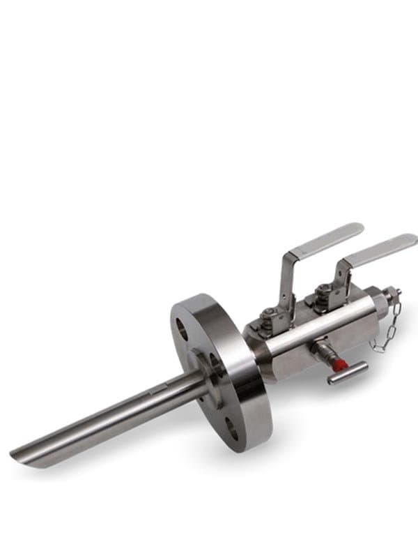
Katup Needle DBB Sampling
Spesifikasi Singkat 1/4" - 1/2" (DN8 - DN15) hingga 10.000 psi / Kelas 150 - 2500 setara API 6D, ISO 15848, NACE MR0175 (konfigurasi layanan asam) A182 F316, A182 F51, A182 F53, Monel (layanan asam NACE) PTFE, PEEK, logam-ke-logam (Stellite 6) Katup jarum sampling dengan isolasi DBB, bodi kompak, sambungan berulir (NPT/BSP), port sampel dengan perlindungan blok ganda Sampling dari Jalur Proses Hidup——dan Mengapa Titik Pengambilan Sampel Membutuhkan Perlindungan DBB Katup sampling mengekstrak volume kecil fluida proses dari pipa hidup untuk analisis laboratorium, verifikasi kualitas, atau pengujian kepatuhan regulasi——sampel harus representatif (komposisi sama, tekanan sama, suhu sama dengan aliran proses utama), dan ekstraksi harus aman (teknisi yang mengambil sampel tidak boleh terpapar tekanan pipa penuh, dan pipa tidak boleh kehilangan penahanan melalui titik pengambilan sampel). Katup sampling blok tunggal sederhana menyediakan satu batas isolasi——ketika katup tertutup, port sampel terisolasi dari pipa. Tetapi isolasi tersebut bersifat titik tunggal: jika dudukan tunggal bocor, tekanan pipa mencapai port sampel dan wadah sampel secara bersamaan——teknisi terkena tekanan proses hidup saat menangani botol sampel yang seharusnya berada pada tekanan atmosfer. Pada aplikasi sampling hidrokarbon, kimia, dan gas asam di mana media proses mudah terbakar, beracun, atau bertekanan tinggi, kegagalan isolasi titik tunggal tersebut adalah insiden keselamatan——bukan hanya masalah kontaminasi sampel. Katup jarum DBB sampling FLOWKS menyediakan isolasi ganda blok dan buang pada titik koneksi sampling——dua dudukan blok katup jarum independen dengan rongga buang di antaranya, dalam bodi kompak yang dipasang langsung pada keran sampling pipa. Katup jarum hulu memblokir tekanan pipa dari rongga buang. Katup jarum hilir memblokir tekanan apa pun yang bocor melewati katup jarum hulu agar tidak mencapai port sampling. Rongga buang di antara kedua katup jarum mengalirkan ke atmosfer atau saluran pembuangan tertutup——tekanan nol pada buang mengonfirmasi kedua katup blok menahan sebelum port sampling dibuka untuk ekstraksi sampel. Arsitektur DBB menyediakan logika isolasi terverifikasi yang sama pada keran sampling yang disediakan pada titik isolasi gauge dan transmitter: Anda memverifikasi isolasi melalui buang sebelum membuka sisi hilir ke atmosfer. Pada sampling proses, langkah verifikasi ini sangat penting karena teknisi akan membuka wadah sampel yang dirancang untuk tekanan atmosfer——Anda tidak mengekspos botol sampel bertekanan atmosfer bahkan ke sedikit tekanan pipa hidup tanpa memverifikasi bahwa isolasi masih utuh. Trim Jarum——Mekanisme Dudukan yang Tepat untuk Ekstraksi Sampel Bore Kecil Volume ekstraksi sampel kecil——beberapa mililiter hingga beberapa ratus mililiter, ditarik melalui port sampling bore 1/4" atau 1/2". Ukuran bore kecil karena volume sampel kecil dan laju ekstraksi perlu dikontrol secara presisi (penarikan sampel cepat menarik fluida yang tidak representatif; penarikan lambat dan terkontrol memberikan komposisi yang representatif). Trim jarum pada bore 1/4"-1/2" memberikan presisi kontrol aliran yang dibutuhkan sampling——plug jarum meruncing memodulasi area aliran secara bertahap saat batang berputar, memberikan teknisi kontrol halus atas laju ekstraksi daripada biner terbuka-tertutup on/off. Kemampuan modulasi itu dibangun ke dalam geometri jarum——jarum tidak hanya membuka dan menutup, tetapi juga mengatur aliran pada posisi parsial di mana area aliran antara ujung jarum dan kerucut dudukan dikontrol secara presisi oleh sudut rotasi batang. Untuk dudukan blok DBB (hulu dan hilir), geometri jarum yang sama memberikan penyegelan baji progresif——penutupan lebih rapat dengan torsi batang tambahan, sama seperti DBB tipe jarum flensa-ke-sekrup. Untuk port ekstraksi sampling (koneksi hilir tempat wadah sampel dipasang), kemampuan throttling jarum memberikan manajemen laju ekstraksi yang terkontrol——teknisi tidak membuka port sampel sepenuhnya dan membiarkan media proses mengalir deras ke dalam wadah dengan kecepatan pipa. Sebaliknya, jarum dibuka secara bertahap, sampel mengalir pada laju terkontrol, wadah terisi perlahan dan stabil, dan komposisi tetap representatif karena laju ekstraksi tidak menciptakan turbulensi atau pemisahan fase preferensial dalam aliran sampel. Prosedur Ekstraksi Sampel——Verifikasi DBB Sebelum Membuka ke Atmosfer Prosedur sampling dengan katup jarum DBB mengikuti urutan yang ditentukan yang dipaksakan secara fisik oleh arsitektur tiga batang: Tutup kedua jarum penyumbat (hulu dan hilir)—port pengambilan sampel sepenuhnya terisolasi dari saluran pipa. Buka katup jarum buang——buang tekanan sisa apa pun di rongga antara kedua katup jarum blok. Periksa tekanan nol pada buang. Nol mengonfirmasi kedua katup jarum blok menahan. Jika buang menunjukkan nol: lanjutkan dengan...
Gambaran Teknis
Katup double block and bleed memberi Anda dua batas penyegelan independen dengan rongga ventilasi yang terverifikasi di antara keduanya. Itu terdengar berlebihan sampai Anda berdiri di samping pengukur tekanan pada saluran hidrokarbon 1500-psi dan melihat satu dudukan isolasi merembeskan fluida proses menuju koneksi instrumen. Satu dudukan bisa bocor. Satu dudukan bisa gagal. DBB menghilangkan risiko itu dengan mensyaratkan dudukan hulu dan hilir untuk menahan secara bersamaan, dengan rongga ventilasi di antara keduanya dibuang ke atmosfer atau saluran pembuangan tertutup sehingga Anda dapat memverifikasi secara visual kedua dudukan menyegel sebelum membuka sisi instrumen. FLOWKS memproduksi konfigurasi DBB tipe gauge block, flange, trunnion, dan jarum—dari katup isolasi instrumen kompak 1/2" hingga unit DBB pipa saluran penuh. Gauge block DBB dipasang langsung di titik sadap instrumen dengan koneksi nonoflange atau berflensa. Flange dan trunnion DBB mengisolasi bagian pipa untuk pemeliharaan, inspeksi, dan verifikasi tekanan. Katup jarum DBB sampling menambahkan port sampel di antara dua dudukan pemblokiran, memungkinkan ekstraksi fluida tanpa memutus isolasi. Setiap konfigurasi DBB berbagi prinsip fungsional yang sama: dua dudukan, satu ventilasi, bukti tekanan-nol terverifikasi bahwa kedua batas menahan sebelum Anda melanjutkan.
Katup double block and bleed (DBB) FLOWKS menyediakan isolasi ganda terverifikasi dengan rongga berventilasi di antara dua batas dudukan independen. Dudukan hulu memblokir tekanan proses; dudukan hilir melindungi instrumen atau saluran hilir; rongga ventilasi di antara keduanya dibuang ke atmosfer atau saluran pembuangan tertutup, memberikan konfirmasi visual bahwa kedua dudukan menahan sebelum pekerjaan hilir dimulai. Katup DBB gauge block nonoflange disekrup langsung ke titik sadap instrumen—1/2" hingga 2", Kelas 150–1500, pemasangan kompak tanpa baut flange atau penyelarasan gasket. Katup SBB (single block and bleed) gauge block menyediakan satu dudukan pemblokiran plus ventilasi untuk aplikasi di mana isolasi ganda tidak diwajibkan. Katup DBB flange dibaut ke koneksi berflensa pipa untuk isolasi diameter lebih besar. Katup DBB trunnion mengintegrasikan fungsi double block and bleed ke dalam badan katup bola terpasang trunnion untuk layanan pipa saluran penuh. Katup DBB tipe jarum flange-ke-sekrup menggabungkan koneksi proses berflensa dengan koneksi instrumen berulir, menjembatani antara standar perpipaan. Katup DBB jarum sampling menambahkan port ekstraksi sampel di dalam rongga ventilasi, memungkinkan pengumpulan fluida tanpa memutus salah satu batas isolasi. Katup DBB FLOWKS memenuhi persyaratan API 6D untuk isolasi ganda, dengan sertifikasi emisi fugitif ISO 15848 tersedia. Opsi dudukan termasuk PTFE, PEEK, dan logam-ke-logam (Stellite 6) untuk kompatibilitas kimia dan pencocokan rentang suhu.
Unduhan Produk
Industri Pengguna Produk Ini
Aplikasi di berbagai sektor industri.
Oil & Gas
Upstream, midstream and downstream valve solutions meeting API 6D, API 607 fire-safe requirements. From wellhead to refinery, FLOWKS provides reliable valve solutions for the most demanding oil and gas applications.
LNG
Cryogenic valves engineered for liquefied natural gas processing and transportation. FLOWKS cryogenic service valves are tested to -196degC per BS 6364.
Refining
Heavy-duty valves designed for the extreme conditions of petroleum refining. FLOWKS valves handle high temperatures, corrosive media, and erosive service in refineries globally.
products.lookingMore
products.lookingMoreDesc
Ball Valves
FLOWKS offers floating ball valve, trunnion mounted ball valve and top entry ball valve for oil & gas, petrochemical and power generation. Designed per API 6D, API 608 and ASME B16.34.
Gate Valves
FLOWKS gate valves for isolation service in piping systems. Flexible wedge, solid wedge, slab and expanding gate designs per API 600, API 602 and ASME B16.34.
Globe Valves
FLOWKS globe valves for throttling and isolation. Standard, angle, Y-pattern and bellows seal configurations per API 602 and BS 1868.
Check Valves
FLOWKS check valves prevent reverse flow. Dual plate, swing, tilting disc and lift check designs per API 594 and BS 1868.