products.productRange
مجموعه کامل شیرهای صنعتی برای تمامی کاربردها.
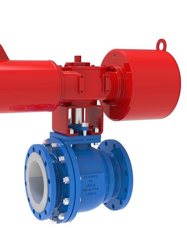
شیر توپی با پوشش PTFE
سایز: ۱/۲" - ۱۲" (DN15 - DN300) فشار: کلاس ۱۵۰ - ۳۰۰ / PN 10-40 استاندارد: MSS SP-111 (آستر پلاستیکی)، مخصوص تولیدکننده برای شیرهای آستردار مواد بدنه: بدنه بیرونی چدن داکتیل (GGG40) یا فولاد کربنی (A216 WCB)؛ آستر تمامبدنه PTFE (۳-۵ میلیمتر) پوششدهنده تمام سطوح خیسشونده — حفره بدنه، سطوح نشیمنگاه، ناحیه تماس توپ نشیمنگاه: آستر PTFE هم بهعنوان آستر بدنه و هم ماده نشیمنگاه عمل میکند — آستر تا سطوح نشیمنگاه برای تماس قطع جریان توپ گسترش مییابد؛ بدون حلقههای نشیمنگاه فلزی جداگانه در معرض سیال فرآیندی طراحی: آستر تمامبدنه PTFE — غلاف پیوسته PTFE قالبگیری/نصب شده در حفره بدنه؛ توپ در ناحیه نشیمنگاه علیه آستر PTFE میچرخد؛ انتهای فلنجدار؛ پوشش بدنه پیچ و مهره شده (بدنه دو تکه یا سه تکه)؛ صفر تماس فلزی با محیطهای خورنده وقتی فولاد ضدزنگ پاسخها تمام میشود شما آنجا بودهاید. برگه مشخصات میگوید 316L. سیال فرآیندی میگوید اسید هیدروکلریک غلیظ. مهندس میگوید "این کار نمیکند." و ناگهان با یک مشکل انتخاب ماده مواجه میشوید که فولاد ضدزنگ، Hastelloy و تیتانیوم همگی از آن کنار میکشند. شیرهای توپی با آستر PTFE دقیقاً برای آن لحظه وجود دارند. طراحی آنچه را که شیرهای توپی استاندارد سعی میکنند در یک ماده انجام دهند — تحمل فشار و مقاومت در برابر خوردگی — به دو لایه اختصاصی جدا میکند. بدنه بیرونی، چدن داکتیل یا فولاد کربنی، فشار خط را نگه میدارد. این کار آن است و آن را خوب انجام میدهد. آستر PTFE، ضخیم در ۳-۵ میلیمتر، هر سطحی را که سیال فرآیندی لمس میکند میپیچد. حفره بدنه. سطوح نشیمنگاه. ناحیهای که توپ برای قطع جریان مینشیند. هیچ چیز به پوسته فلزی زیرین نفوذ نمیکند. آن جداسازی بیشتر از آنچه بیشتر برگههای مشخصات اعتراف میکنند اهمیت دارد. صفر تماس فلزی یعنی صفر حمله خوردگی به بدنه. صفر یونهای فلزی آلودهکننده محیط فرآیندی شما. صفر نگرانیهای خوردگی گالوانیکی بین فلزات غیرهمجنس در همان خط لوله. شما مجبور نیستید به هیچکدام فکر کنید — آستر PTFE شیمی را مدیریت میکند، بدنه فلزی فیزیک را مدیریت میکند. شیمی که PTFE پوشش میدهد PTFE از نظر شیمیایی تقریباً در برابر تمام محیطهای خورنده صنعتی که با آنها مواجه میشوید بیاثر است. اسید هیدروکلریک غلیظ در هر دمایی. اسید سولفوریک تا بالای ۷۰٪. گاز کلر. بیشتر اکسیدکنندههای قوی. حلالهای آلی در طیف دارویی. استثناها عجیب و غریب هستند — فلزات قلیایی مذاب و فلوئور عنصری در دماهای بالا. اگر فرآیند شما شامل هر یک از آن دو باشد، به گفتگوی متفاوتی نیاز دارید. برای هر چیز دیگری که فلز را میخورد، PTFE سدی است که واقعاً کار میکند. آستر یک پوشش نیست آن را آستر بنامید، نه پوشش. پوششها نازک هستند — با میکرون اندازهگیری میشوند و با اسپری یا غوطهوری اعمال میشوند. آنها ترک میخورند. سوراخ سوزنی پیدا میکنند. در نقاط تنش مکانیکی مانند تماسهای نشیمنگاه شکست میخورند. آستر PTFE در این شیرها ۳ تا ۵ میلیمتر ضخامت دارد و بهصورت یک غلاف پیوسته قالبگیری میشود که حفره بدنه را پر میکند. این ضخامت به شما دوام مکانیکی واقعی در ناحیه نشیمنگاه میدهد، جایی که گوی در هر سیکل آستر را فشرده میکند. آستر فقط در برابر خوردگی مقاومت نمیکند — بلکه تحت نیروی نشست مکرر بدون نازک شدن تا حد شکست، پابرجا میماند. ایزولاسیون کامل جریان، نه محافظت جزئی آستر PTFE تمام سطوح در تماس با سیال داخل بدنه را میپوشاند. نه فقط مسیر جریان — بلکه حفره بدنه پشت گوی، ناحیه تماس نشیمنگاه، و محلی که سیال فرآیندی هنگام بسته بودن شیر در آن قرار میگیرد. خود گوی در برابر PTFE میچرخد، نه فلز. هیچ جزء فلزی در تماس با سیال در این شیر وجود ندارد. این تعریف ایزولاسیون کامل است و به همین دلیل است که تولیدکنندگان مواد شیمیایی، سازندگان داروسازی، و مهندسان سرویس رسانههای خورنده، شیرهای توپی با آستر PTFE را مشخص میکنند، در حالی که جایگزین این است که بپذیریم هر گزینه فلزی در نهایت شکست خواهد خورد. پاسخ: توصیه نمیشود. PTFE بالای ۲۰۰ درجه سانتیگراد شروع به نرم شدن میکند و در دماهای پایدار بالای ۲۶۰ درجه سانتیگراد استحکام مکانیکی خود را از دست میدهد. سرویس بخار، بهویژه بخار اشباع تحت فشار، از ظرفیت حرارتی PTFE فراتر میرود. برای بخار از شیرهای با نشیمنگاه فلزی استفاده کنید. پاسخ: بدنه بیرونی هرگز با سیال فرآیندی تماس پیدا نمیکند. وظیفه آن استحکام ساختاری و مهار فشار است که هر دو توسط چدن داکتیل و فولاد کربنی بهصرفه تأمین میشوند. وقتی آستر PTFE ایزولاسیون کامل را فراهم میکند، به پوسته بیرونی مقاوم در برابر خوردگی نیازی ندارید. پاسخ: آسیب آستر در سطح فلنج یا ناحیه واشر میتواند مسیر مستقیمی برای رسیدن رسانههای خورنده به بدنه فلزی ایجاد کند. قبل از پیچکردن، سطوح آستر را بازرسی کنید. از مونتاژ فلنج با کنترل گشتاور استفاده کنید — فشار بیش از حد میتواند آستر را در ناحیه واشر له کند. پاسخ: آسترهای PTFE میتوانند خلأ را تحمل کنند، اما اگر طراحی حفره بدنه پشتیبانی کافی برای آستر فراهم نکند، آستر ممکن است تحت خلأ پایدار به سمت داخل تغییر شکل دهد. برای طرحهای مقاوم به خلأ با سازنده مشورت کنید — هندسه بدنه اهمیت دارد. پاسخ: نشیمنگاههای با آستر PTFE معمولاً قطع جریان کلاس IV یا بهتر را محقق میکنند. آستر PTFE تحت نیروی نشست گوی فشرده میشود و یک آببند نشیمنگاه نرم ایجاد میکند که در بیشتر شرایط از نشیمنگاههای سخت فلز-به-فلز محکمتر است. اگر آستر از سیکلهای مکرر نازک شود، نشتی افزایش مییابد — آن زمان است که تعویض لازم است.
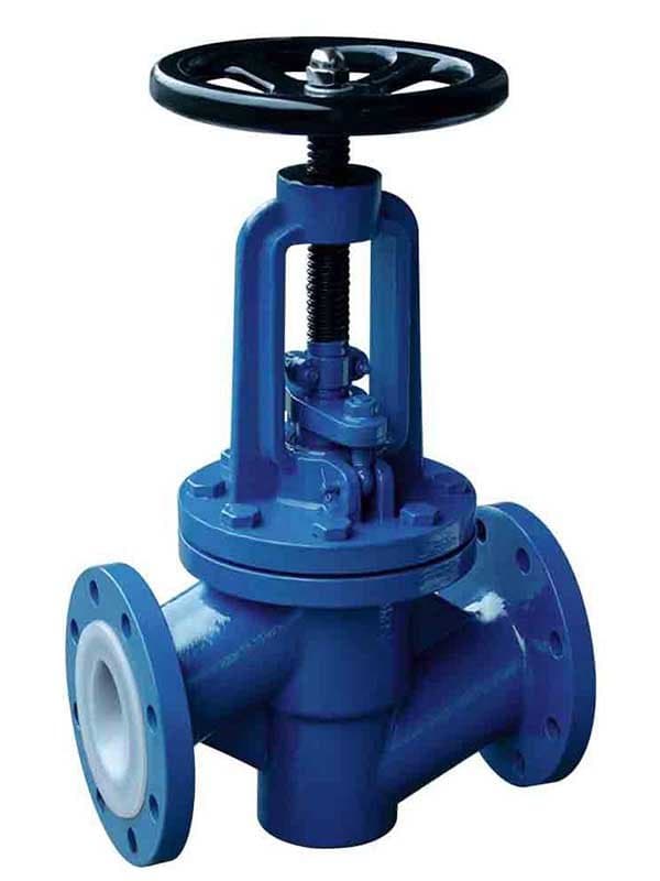
شیر کروی با پوشش PFA
سایز: ۱/۲ اینچ تا ۸ اینچ (DN15 تا DN200) فشار: کلاس ۱۵۰ تا ۳۰۰ / PN 10-40 استاندارد: MSS SP-111، مخصوص سازنده مواد بدنه: فولاد کربنی (A216 WCB) یا بدنه بیرونی چدن داکتیل؛ آستر تمامبدنه PFA (پرفلوروآلکوکسی) (۳ تا ۵ میلیمتر) که تمام سطوح در تماس با سیال را میپوشاند — سوراخ بدنه، ناحیه حلقه نشیمنگاه، سطح تماس دیسک، داخل بونیت تا ناحیه پکینگ نشیمنگاه: آستر PFA تا ناحیه حلقه نشیمنگاه برای تماس قطع جریان دیسک امتداد مییابد؛ دیسک با PFA روکش شده است — هسته فلزی برای استحکام ساختاری، پوسته PFA برای ایزولاسیون خوردگی طراحی: بدنه شیر گلوب با آستر PFA؛ دیسک برای تنظیم جریان و قطع جریان از نشیمنگاه بلند میشود؛ PFA هر سطح در تماس با سیال را میپوشاند — هیچ فلز نمایانی در مسیر جریان وجود ندارد چرا PFA، نه PTFE، برای شیرهای گلوب هر دو ماده از نظر شیمیایی نسبت به همان طیف رسانههای خورنده بیاثر هستند. PTFE ارزانتر، اثباتشده و کارآمد است. بیشتر شیرهای آستردار در صنعت از آستر PTFE استفاده میکنند. پس چرا برای شیر گلوب PFA مشخص کنیم؟ به نحوه عملکرد شیرهای گلوب برمیگردد. آنها تنظیم جریان میکنند. دیسک فقط مثل شیر توپی باز و بسته نمیشود — بلکه جریان را تعدیل میکند و در هر سیکل روی سطح نشیمنگاه میلغزد. صدها سیکل. هزاران سیکل. و هر بار که آن دیسک با آستر PTFE در نشیمنگاه تماس پیدا میکند، دو مشکل ظاهر میشود. اول: جریان سرد. PTFE تحت بار مکانیکی پایدار خزش میکند. نیروی نشست، PTFE را در ناحیه تماس دیسک-نشیمنگاه فشرده میکند. در طول صدها سیکل، این فشردگی آستر را نازک میکند تا جایی که نمیتواند فشار قطع جریان را حفظ کند. آن را بهصورت افزایش نشتی نشیمنگاه در طول زمان میبینید — آستر به معنای واقعی کلمه با هر سیکل بسته شدن نازکتر میشود. دوم: پرداخت سطح. آسترهای PTFE با قالبگیری فشاری یا اکستروژن خمیری ساخته میشوند. سطح آن به اندازهای که میتواند باشد صاف نیست. سطح زبرتر به معنای اصطکاک بیشتر در تماس لغزشی دیسک-به-نشیمنگاه است که سایش را هم روی روکش دیسک و هم ناحیه آستر نشیمنگاه تسریع میکند. PFA هر دو را حل میکند. خزش آن تحت بار تقریباً ۱۰ برابر کمتر از PTFE است — ناحیه نشیمنگاه شکل ابعادی خود را در طول هزاران سیکل تنظیم جریان حفظ میکند. و قابلیت فرآیندپذیری مذاب PFA سطح آستر صافتر و یکنواختتری تولید میکند که اصطکاک لغزشی را در فصل مشترک دیسک-نشیمنگاه کاهش میدهد. بدهبستان هزینه است. مواد آستر PFA ۳۰ تا ۵۰ درصد بیشتر از PTFE هزینه دارد. اما برای یک شیر گلوب تنظیم جریان در سرویس خورنده که جفت دیسک-نشیمنگاه هزاران بار سیکل میزند، آن تفاوت هزینه برای شما آستری میخرد که قبل از اینکه نشتی نشیمنگاه تعویض را الزامی کند، سیکلهای بیشتری را تحمل میکند. این محاسبه است — نه اینکه کدام ماده به ازای هر کیلوگرم ارزانتر است، بلکه کدام ماده شیر را بین تعویضهای آستر مدت طولانیتری در سرویس نگه میدارد. دیسک بخشی از سیستم آستر است دیسک گلوب فقط روی سطح تماس با PFA آستر نشده است. بلکه با PFA روکش کامل شده است — هسته فلزی، پوسته PFA که تمام سطح دیسک را میپوشاند. دیسک دقیقاً مثل سوراخ بدنه داخل سیال فرآیندی زندگی میکند. دیسکی که PFA فقط روی سطح نشیمنگاه داشته باشد، فلز را در جاهای دیگر در معرض رسانههای خورنده قرار میدهد. آن ایزولاسیون کامل نیست. روکش کامل PFA به این معنی است که دیسک به اندازه آستر بدنه از نظر شیمیایی ایزوله است — بدون فلز، بدون خوردگی، بدون آلودگی از سمت دیسک. تنظیم جریان در جایی که هیچ چیز دیگری دوام نمیآورد شیرهای گلوب با آستر PFA در سرویسهای تنظیم جریان خورنده کاربرد دارند که شیرهای گلوب با نشیمن فلزی نمیتوانند عمل کنند — کنترل غلظت اسید، تنظیم جریان سوزآور، اندازهگیری حلالهای دارویی، تنظیم خوراک راکتور شیمیایی. این سرویس هم مقاومت در برابر خوردگی و هم دقت تنظیم جریان را میطلبد. PFA روی آستر و دیسک، سد خوردگی را فراهم میکند. هندسه دیسک-به-نشیمن گلوب، کنترل تنظیم جریان را میدهد. با هم، کاری را انجام میدهند که نه شیر توپی آستردار (ایزولاسیون عالی، تنظیم ضعیف) و نه شیر گلوب فلزی (تنظیم عالی، مقاومت خوردگی صفر) بهتنهایی نمیتوانند انجام دهند. پاسخ: میتوانید، اما برای آن نقش بیش از حد مشخصات دارد. اگر فقط به قطع جریان در سرویس خورنده نیاز دارید، شیر توپی با آستر PTFE سادهتر و کمهزینهتر است. شیرهای گلوب زمانی جایگاه خود را پیدا میکنند که تنظیم جریان بخشی از الزامات باشد. پاسخ: بستگی به نیروی نشیمن، مسافت حرکت دیسک و دمای فرآیند دارد. در سرویس تنظیم اسید معمولی در دماهای محیطی تا متوسط، آسترهای PFA پایداری ابعادی را تا چند هزار سیکل کامل حفظ میکنند. نشتی نشیمن را پایش کنید — وقتی روند آن به بالاتر از کلاس IV رفت، آستر در ناحیه نشیمن در حال نازک شدن است و زمان تعویض فرا رسیده است. پاسخ: اساساً بله. PFA و PTFE در برابر همان طیف رسانههای خورنده مقاومت میکنند — اسیدهای قوی، اکسیدکنندهها، هالوژنها، حلالهای آلی. حداکثر دمای سرویس پیوسته PFA کمی کمتر از PTFE است (۲۶۰ درجه سانتیگراد در مقابل ۲۸۰ درجه سانتیگراد)، اما در آن محدوده، پروفایل مقاومت شیمیایی معادل است. پاسخ: پکینگ PTFE یا PFA بالای ناحیه آستر بوننت، با میله مقاوم در برابر خوردگی که در محل عبور از سوراخ بوننت نیز با PFA پوشیده شده است. ناحیه پکینگ نقطه انتقال است — آستر داخل بوننت را تا ناحیه پکینگ میپوشاند و پکینگ میله را بالای آن نقطه آببندی میکند. پاسخ: نه در محل نصب. آسترهای PFA در حفره بدنه قالبگیری میشوند — برداشتن و تعویض آستر نیاز به آسترکاری مجدد در کارخانه دارد. روند نشتی نشیمن را پایش کنید و تعویض شیر یا آسترکاری مجدد کارخانه را زمانی برنامهریزی کنید که نشتی از حد مجاز فراتر...
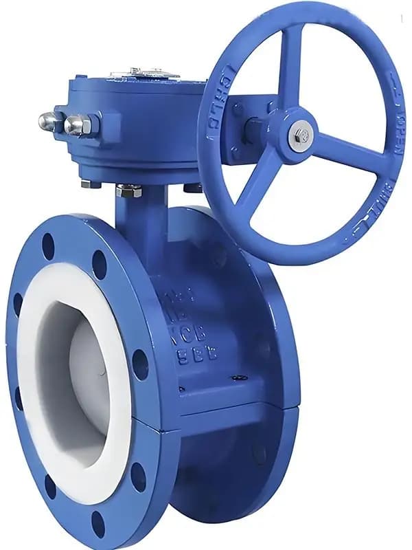
شیر پروانهای با پوشش PTFE
سایز: ۲ اینچ - ۲۴ اینچ (DN50 - DN600) فشار: کلاس ۱۵۰ / PN 10-16 استاندارد: API 609 (پروانهای)، MSS SP-111 مواد بدنه: بدنه خارجی چدن داکتیل یا فولاد کربنی؛ آستر غلافی تمامبدنه PTFE که سطح سوراخ بدنه را میپوشاند و تا ناحیه نشیمن دیسک امتداد مییابد؛ دیسک فلزی (استیل ضدزنگ یا چدن داکتیل) با پوشش PTFE روی لبه آببند، یا لبه دیسک مستقیماً روی آستر بدنه PTFE مینشیند طراحی: دیسک پروانهای مرکزی با آستر بدنه PTFE؛ دیسک ۹۰ درجه داخل سوراخ آستردار PTFE میچرخد؛ آستر PTFE کل سطح سوراخ را میپوشاند — لبه دیسک برای قطع جریان روی آستر فشرده میشود؛ فرم بدنه ویفر یا لَگ لوله بزرگ، رسانه خورنده، هزینه واقعبینانه مشکل اقتصادی در سرویس خورنده در قطرهای بزرگ این است. یک شیر توپی با آستر PTFE سایز ۱۰ اینچ کار میکند — فرآیند را ایزوله میکند، شیمی را حفظ میکند، تمیز قطع میکند. همچنین سه برابر شیر پروانهای با آستر PTFE سایز ۱۰ اینچ هزینه دارد، زیرا آسترکاری حفره بدنه شیر توپی گران است. بدنه شیر توپی هندسه داخلی پیچیدهای دارد — سوراخ، حفره پشت توپ، جیبهای نشیمن، سطح اتصال پوشش بدنه. PTFE باید همه آن را بهصورت آستر پیوسته پر کند. در قطر ۱۰ اینچ، این مقدار زیادی قالبگیری PTFE در شکل پیچیده زیاد است. بدنه شیر پروانهای سادهتر است. سوراخ کوتاه مستقیم. دیسک چرخان. آستر PTFE سطح سوراخ را بهصورت غلاف میپوشاند — هندسه سادهتر، قالبگیری و نصب آسانتر، مواد کمتر، کار کمتر، هزینه کمتر. مصالحه در رتبه فشار و دقت قطع جریان است، نه ایزولاسیون خوردگی. همان سد شیمیایی PTFE را در سطح سوراخ دریافت میکنید. همان ایزولاسیون بدون تماس فلزی را برای سیال فرآیند دریافت میکنید. آن را با هزینهای دریافت میکنید که سرویس خورنده در قطر بزرگ را از نظر اقتصادی مقرونبهصرفه میکند. کلاس ۱۵۰ — محدودیت واقعی است شیرهای پروانهای با آستر PTFE در کلاس ۱۵۰ به حداکثر میرسند. این یک رتبه محافظهکارانه یا محدودیت بازاریابی نیست — حد فیزیکی چیزی است که آستر PTFE میتواند تحت فشار نشیمن دیسک تحمل کند. در کلاس ۳۰۰، لبه دیسک آستر PTFE را در ناحیه نشیمن با نیرویی فشرده میکند که آستر فراتر از بازیابی الاستیک خود تغییر شکل میدهد. PTFE انعطافپذیر است، نه صلب. در کلاس ۱۵۰ آببندی میکند زیرا نیروی نشیمن در محدودهای میماند که PTFE فشرده و بازمیگردد. بالای آن محدوده، فشرده میشود و فشرده میماند — ناحیه نشیمن نازک میشود، لبه دیسک در آستر فرو میرود و قطع جریان بهسرعت افت میکند. برای سرویس شیمیایی خورنده کلاس ۱۵۰، آن محدودیت مشکلی نیست. خطوط انتقال اسید، توزیع کلر، گردش سوزآور، سیستمهای حلال دارویی — اینها در کلاس ۱۵۰ یا کمتر کار میکنند. شیر پروانهای با آستر PTFE همه آنها را با قیمتی مدیریت میکند که آسترکاری لولههای قطر بزرگ را واقعبینانه میسازد. استراتژی آببندی دیسک لبه آببند دیسک یا پوشش PTFE بهصورت پوسته دور لبه دیسک فلزی دارد، یا لبه دیسک برهنه مستقیماً روی آستر بدنه PTFE مینشیند. لبههای دیسک با پوشش PTFE آببندی نرمتر و سازگارتر فراهم میکنند — پوسته PTFE روی آستر PTFE فشرده میشود و تماس دوسهنرم ایجاد میکند که در نیروی نشیمن کمتر محکمتر است. تماس مستقیم لبه دیسک فلزی روی آستر PTFE نیز کار میکند — لبه فلزی خط آببندی تمیزی در سطح PTFE ایجاد میکند. هر دو روش آببندی میکنند. نسخه پوششدار در طول سیکلهای بیشتر روی سطح آستر ملایمتر است. نسخه تماس مستقیم سادهتر و در اولین بسته شدن کمی محکمتر است. جایی که این شیر منطقی است هدرهای توزیع اسید کارخانه شیمیایی در قطرهای ۸، ۱۰، ۱۲ اینچ. خطوط اصلی انتقال حلال دارویی. حلقههای گردش کارخانه پردازش کلر. هر سرویس خورنده در کلاس ۱۵۰ که قطر لوله، شیر توپی آستردار را از نظر هزینه غیرقابل توجیه میکند. این قلمرو شیر پروانهای با آستر PTFE است — سوراخ بزرگ، رسانه خورنده، فشار متوسط، ایزولاسیون مقرونبهصرفه. الف: محدودسازی جریان (تراتلینگ) امکانپذیر است، اما شیرهای پروانهای در خدمات خورنده با آستر، عمدتاً شیرهای قطع و وصل هستند. تراتلینگ در زوایای جزئی دیسک به این معناست که لبه دیسک در حالت فشرده برای مدت طولانی روی آستر PTFE قرار میگیرد — این فشار مداوم، نازکشدن آستر را در ناحیه تماس تسریع میکند. برای تراتلینگ پیوسته از شیرهای گلوب آستردار استفاده کنید. الف: بدنههای ویفر سبکتر و ارزانتر هستند و بین فلنجها با پیچهای عبوری قرار میگیرند. بدنههای لَگ دارای لَگهای رزوهای برای هر طرف فلنج هستند که امکان جداسازی فلنج یک طرف را بدون شکستن طرف مقابل فراهم میکند. برای نصبهایی که دسترسی تعمیراتی دارند و ممکن است نیاز به ایزوله کردن یک طرف داشته باشید، نوع لَگ را مشخص کنید. برای قطع و وصل ساده بین دو فلنج ثابت، نوع ویفر مناسب است. الف: مواد آستر PTFE برای سرویس پیوسته تا ۲۰۰ درجه سانتیگراد مناسب است، با تحمل پیک تا ۲۶۰ درجه سانتیگراد برای دورههای کوتاه. بالای ۲۰۰ درجه سانتیگراد به صورت مداوم، PTFE شروع به نرم شدن میکند و توانایی آستر برای حفظ نیروی نشیمنگاه در لبه دیسک کاهش مییابد. برای سرویس با فشار نامی، زیر ۲۰۰ درجه سانتیگراد بمانید. الف: آستر PTFE تا سطح فلنج امتداد دارد. همچنان باید از گسکت بین سطح فلنج شیر و فلنج لوله استفاده کنید — گسکت مکمل سطح آستر است، نه جایگزین آن. مواد گسکت را با شیمی فرآیند مطابقت دهید. گسکتهای پوششی PTFE با فیلر انعطافپذیر برای اتصالات فلنج شیرهای آستردار رایج هستند. الف: نشتی نشیمنگاه را در طول آزمایشهای دورهای پایش کنید. وقتی نشتی در حالت بسته از حد کلاس VI (برای شیرهای با نشیمنگاه نرم) فراتر رود یا در آزمایشهای متوالی روند افزایشی داشته باشد، آستر PTFE در ناحیه تماس لبه دیسک در حال نازک شدن است. شیر نیاز به آسترکشی مجدد در کارخانه یا...
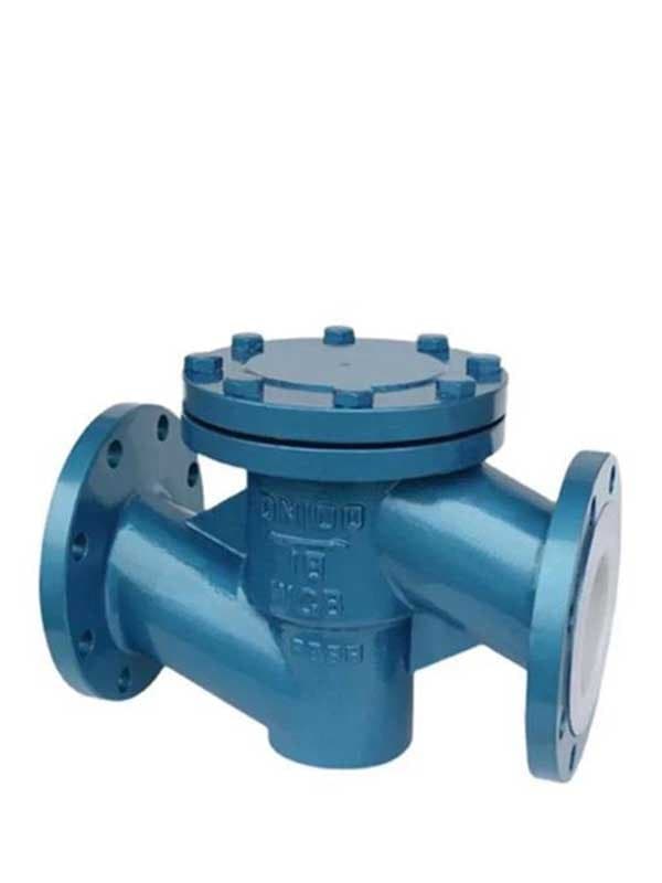
شیر یکطرفه با پوشش FEP
سایز: ۱ تا ۱۲ اینچ (DN25 تا DN300) فشار: کلاس ۱۵۰ تا ۳۰۰ / PN 10-40 استاندارد: MSS SP-111، اختصاصی سازنده مواد بدنه: فولاد کربنی (A216 WCB) یا بدنه خارجی چدن داکتیل؛ آستر تمامبدنه FEP (فلوئورواتیلن پروپیلن) (۲-۴ میلیمتر) که تمام سطوح خیسشونده را میپوشاند — حفره بدنه، ناحیه نشیمنگاه، سطح تماس دیسک، محفظه پین لولا مکانیزم یکطرفه: نوع چرخشی (دیسک روی پین لولا میچرخد) یا نوع بالارونده (دیسک به صورت عمودی از نشیمنگاه بلند میشود)؛ دیسک و پین لولا با FEP روکش شدهاند — هسته فلزی برای استحکام، پوسته FEP برای ایزوله خوردگی؛ هیچ فلز نمایانی روی هیچ قطعه خیسشوندهای وجود ندارد طراحی: بدنه شیر یکطرفه با آستر FEP؛ جلوگیری از جریان یکطرفه؛ دیسک چرخشی یا بالارونده داخل حفره آستردار FEP؛ دیسک با جریان رو به جلو باز میشود و با جریان معکوس بسته میشود مزیت پرداخت سطح آستر FEP برای شیرهای یکطرفه درباره مقاومت شیمیایی نیست — PTFE و FEP همان طیف رسانههای خورنده را پوشش میدهند و هر دو کار میکنند. درباره دینامیک مکانیکی است. پرداخت سطح. شیرهای یکطرفه بر اساس تمیزی باز و بسته شدن دیسک موفق یا ناموفق هستند. دیسک یکطرفه چرخشی روی پین لولا داخل حفره بدنه میچرخد. هر بار که جریان رو به جلو دیسک را باز میکند، لولا میچرخد. هر بار که جریان معکوس دیسک را میبندد، دیسک به سمت نشیمنگاه برمیگردد. اصطکاک در آن دو نقطه تماس — چرخش لولا و تماس مجدد با نشیمنگاه — تعیین میکند که آیا شیر با سرعت جریان صحیح باز میشود و با فشار جریان معکوس صحیح بسته میشود. قالبگیری ذوبی FEP پرداخت سطحی تولید میکند که به طور محسوسی صافتر از PTFE قالبگیری فشاری است. آن سطح صاف اصطکاک را در محفظه پین لولا و در ناحیه تماس دیسک با نشیمنگاه کاهش میدهد. دیسک با مقاومت کمتر باز میشود — در سرعت جریان رو به جلوی پایینتر زودتر باز میشود، که به معنای افت فشار کمتر در عرض شیر در طول جریان عادی است. و در بسته شدن تمیزتر مینشیند — دیسک با کشش کمتر به نشیمنگاه آستر FEP برخورد میکند، بنابراین سریعتر و محکمتر در برابر جریان معکوس بسته میشود. برای شیرهای یکطرفه که دینامیک باز و بسته شدن بخشی از مشخصات عملکرد است — حفاظت تخلیه پمپ اسید، جلوگیری از جریان معکوس راکتور شیمیایی، ایزولهسازی برگشت آب خنککننده خورنده — آن سطح صافتر یک مزیت عملکردی است، نه زیبایی. پوسته سبکتر، دینامیک بهتر FEP کمی چگالی کمتری نسبت به PTFE دارد — تقریباً ۲.۱۵ گرم بر سانتیمتر مکعب در مقابل ۲.۲ گرم بر سانتیمتر مکعب. روی دیسک شیر یکطرفه با هسته فلزی، تفاوت در وزن کل دیسک کوچک اما قابل اندازهگیری است. دیسکهای یکطرفه چرخشی به جرم کافی برای بسته شدن مطمئن در برابر جریان معکوس نیاز دارند، اما جرم اضافی به این معناست که دیسک به سرعت جریان رو به جلوی بیشتری برای باز شدن نیاز دارد. روکش FEP دیسکی به شما میدهد که در پوسته کمی سبکتر است، با جریان رو به جلو کمی راحتتر بلند میشود، و همچنان در هسته فلزی به اندازه کافی سنگین است تا در برابر فشار معکوس بنشیند. این یک بهینهسازی کوچک است، اما دینامیک شیر یکطرفه یک بازی با حاشیه کم است — جرم دیسک و اصطکاک سطح با هم تعیین میکنند که شیر کار میکند یا چکش آبی ایجاد میشود. FEP در مقابل PTFE — همان شیمی، مکانیک بهتر هر دو ماده در برابر همان رسانههای خورنده مقاومت میکنند. اسیدهای غلیظ. هالوژنها. اکسیدکنندهها. حلالهای آلی. مواد شیمیایی فرآیند دارویی. اگر فرآیند به فلز حمله کند، FEP آن را متوقف میکند همانطور که PTFE متوقف میکند. انتخاب بین آنها در سرویس شیر یکطرفه مکانیکی است، نه شیمیایی. پرداخت سطح صافتر FEP و چگالی اندکی کمتر، دینامیک دیسک را بهتر میکند — باز شدن تمیزتر، بسته شدن تمیزتر، اصطکاک کمتر در لولا و نشیمنگاه. PTFE کار میکند. FEP کمی بهتر کار میکند جایی که مکانیک شیر یکطرفه اهمیت دارد. معاوضه: مواد آستر FEP گرانتر از PTFE است، و حداکثر دمای سرویس پیوسته FEP (۲۰۰ درجه سانتیگراد) کمتر از PTFE (۲۶۰ درجه سانتیگراد) است. اگر سرویس خورنده شما بالای ۲۰۰ درجه سانتیگراد کار میکند، PTFE تنها گزینه است. اگر زیر ۲۰۰ درجه سانتیگراد کار میکند و دینامیک شیر یکطرفه بخشی از الزامات عملکرد شماست، آستر FEP انتخاب بهتری است. هر قطعه خیسشونده، پوشیده شده دیسک، پین لولا، ناحیه نشیمنگاه، بدنه داخلی، داخل بونِت — FEP همه را پوشش میدهد. هیچ سطح فلزی در مسیر جریان وجود ندارد. پین لولا با FEP کپسوله شده است، نه فقط پوشش داده شده. دیسک در تمام سطح خود با FEP کپسوله شده است، نه فقط در سطح نشیمنگاه. ایزولاسیون کامل یعنی سیال خورنده هرگز به فلز نمیرسد، هرگز به مکانیزم لولا حمله نمیکند، و هرگز فرآیند را با یونهای فلزی از هسته دیسک آلوده نمیکند. این همان اصل ایزولاسیون در تمام شیرهای لاینینگدار این خانواده است — فقط برای اجزای متحرک خاص شیر یکطرفه اعمال شده است. پاسخ: نوع سوینگچک برای سایزهای بزرگتر و افت فشار کمتر مؤثرتر عمل میکند. نوع لیفتچک بسته شدن سریعتر و آببندی محکمتری ارائه میدهد اما افت فشار بالاتری دارد و به سایزهای کوچکتر محدود میشود. برای خطوط تخلیه پمپ اسید در سایز ۴ اینچ و بالاتر، سوینگچک استاندارد است. برای ایزولاسیون راکتورهای با قطر کم، لیفتچک مناسب است. پاسخ: جریان ضربانی باعث چرخه سریع دیسک میشود — باز-بسته-باز-بسته با هر ضربه پمپ. این امر سایش را در نواحی تماس دیسک-نشیمنگاه و لولا روی لاینینگ FEP تسریع میکند. نصب یک ضربهگیر (پالسشن دامپنر) در بالادست را در نظر بگیرید، یا طراحی لیفتچک را مشخص کنید که در آن حرکت دیسک کوتاهتر و سایش چرخهای کاهش یابد. پاسخ: بستگی به سایز و جرم دیسک دارد. طراحیهای معمول سوینگچک در سرویس خورنده به سرعت جریان رو به جلوی ۱-۲ متر بر ثانیه نیاز دارند تا...
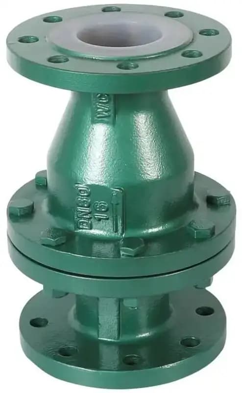
شیرهای یکطرفه نوع توپی عمودی با پوشش فلوئور
سایز: ۱/۲ اینچ - ۴ اینچ (DN15 - DN100) فشار: کلاس ۱۵۰ - ۳۰۰ / PN 10-40 استاندارد: MSS SP-111، مخصوص تولیدکننده مواد بدنه: بدنه خارجی فولاد کربنی یا چدن داکتیل؛ لاینینگ فلوئور (PTFE یا PFA) پوششدهنده تمام سطوح خیسشونده — بدنه داخلی، ناحیه نشیمنگاه، داخل محفظه توپ مکانیزم یکطرفه: توپ شناور آزاد داخل بدنه عمودی؛ توپ در حالت بدون جریان روی نشیمنگاه در پایین قرار میگیرد (بسته)؛ جریان رو به جلوی رو به بالا توپ را از نشیمنگاه به محفظه بالایی بلند میکند (باز)؛ جریان معکوس رو به پایین توپ را به نشیمنگاه برمیگرداند (بسته)؛ توپ از PTFE جامد یا هسته فلزی با کپسولاسیون PTFE است طراحی: فقط نصب عمودی — بدنه به صورت عمودی با جریان رو به بالا؛ محفظه توپ بالای نشیمنگاه؛ توپ تنها قطعه متحرک است؛ بدون لولا، بدون فنر، بدون مکانیزم راهنما؛ عملکرد صرفاً با گرانش + نیروی جریان این سادهترین مکانیزم شیر یکطرفه موجود است. یک توپ. روی نشیمنگاه مینشیند. جریان رو به جلو آن را بلند میکند. جریان معکوس آن را به پایین برمیگرداند. گرانش آن را میبندد. این کل توالی عملکرد است — بدون پین لولا، بدون فنر، بدون میله راهنما، بدون اتصال مکانیکی بین اجزا. در سرویس خورنده، سادگی یعنی بقا. هر جزء مکانیکی در شیر یکطرفه سوینگچک یک نقطه شکست بالقوه است. پین لولا زیر لاینینگ خورده و قفل میشود. بازوی دیسک در اتصال لولا خسته میشود. فنر در طراحی فنردار در محیط خورنده داغ خاصیت خود را از دست میدهد. هر یک از این شکستها با رسیدن سیال خورنده به هسته فلزی داخل لاینینگ شروع میشود — این اتفاق در نقاط تنش، در نواحی خمش، و در اتصالات مکانیکی که لاینینگ نازکتر است یا فلز بیشتر در معرض قرار دارد، رخ میدهد. شیر یکطرفه توپی تمام این اتصالات را حذف میکند. بدون لولا. بدون فنر. بدون راهنما. توپ در یک محفظه قرار دارد، وقتی جریان آن را به بالا هل میدهد بلند میشود، وقتی گرانش و جریان معکوس آن را به پایین هل میدهند سقوط میکند. تنها نقطه سایش، تماس توپ-به-نشیمنگاه است — یک تماس فشاری ساده روی سطح نشیمنگاه لاینینگدار PTFE یا PFA. این یک ناحیه تماس است به جای چهار یا پنج ناحیه. نواحی تماس کمتر یعنی مکانهای کمتر برای ایجاد مسیر نشتی توسط سایش لاینینگ. اجزای مکانیکی کمتر یعنی چیزهای کمتری که میتوانند خراب شوند. گزینههای توپ — PTFE جامد یا هسته فلزی توپهای PTFE جامد برای سیالات خورنده تمیز مناسب هستند. آنها سبکوزن هستند، به طور تمیز روی نشیمنگاه لاینینگدار PTFE آببندی میکنند، و هسته فلزی ندارند که هرگز بتواند در معرض قرار گیرد. محدودیت: توپهای PTFE سبک هستند. در سرویس با سرعت جریان کم یا سیالات چسبناک، توپ ممکن است به اندازه کافی سریع در برابر جریان معکوس بسته نشود زیرا جرم آن کم است. توپهای PTFE با هسته فلزی این مشکل را حل میکنند. هسته فولاد ضدزنگ یا چدن داکتیل داخل کپسولاسیون PTFE جرم بیشتری به توپ میدهد — سریعتر در برابر جریان معکوس بسته میشود و با نیروی بیشتری مینشیند برای آببندی محکمتر. کپسولاسیون PTFE هسته فلزی را از سیال فرآیند ایزوله میکند، همانطور که لاینینگ بدنه پوسته خارجی را ایزوله میکند. معاوضه: اگر کپسولاسیون PTFE هرگز آسیب ببیند — توسط سیال ساینده، ضربه، تنش چرخه حرارتی — هسته فلزی در معرض قرار میگیرد. توپهای PTFE جامد آن آسیبپذیری را ندارند. برای سیالات خورنده کثیف یا چسبناک که نیروی بسته شدن مهم است، توپهای هسته فلزی را انتخاب کنید. برای سیالات خورنده تمیز که حداکثر ایزولاسیون مهم است، توپهای PTFE جامد را انتخاب کنید. فقط عمودی — نه نصب انعطافپذیر شیرهای یکطرفه توپی بهصورت عمودی نصب میشوند و جریان باید رو به بالا باشد. تمام. نمیتوانید آنها را افقی نصب کنید، چون در حالت افقی گرانش توپ را روی نشیمنگاه فشار نمیدهد — توپ صرفنظر از جهت جریان در کف محفظه میماند و شیر هرگز بسته نمیشود. نمیتوانید آنها را با جریان رو به پایین نصب کنید، چون توپ هرگز از نشیمنگاه بلند نمیشود — گرانش آن را پایین نگه میدارد و جریان رو به جلو (رو به پایین) آن را محکمتر به پایین فشار میدهد. این محدودیت نصب، محل استفاده از این شیرها را محدود میکند. خطوط خورنده افقی همچنان به طراحی یکطرفه لولایی یا بالابرنده نیاز دارند. اما خطوط تخلیه عمودی پمپ، حفاظت عمودی جریان رو به بالا در راکتور، و ایزولهسازی عمودی برجهای فرآیندی — اینها نصبهایی هستند که شیر یکطرفه توپی مزیت سادگی خود را ارائه میدهد. اگر سرویس خورنده شما عمودی است، این شیر یکطرفه با کمترین حالتهای خرابی موجود است. حالتهای خرابی کمتر، عمر سرویس بیشتر تحلیل حالت خرابی ساده است. شیر یکطرفه لولایی در سرویس با آستر خورنده حداقل چهار ناحیه خرابی بالقوه دارد: پین لولا، اتصال لولا، بازوی دیسک، و تماس نشیمنگاه. شیر فنردار، فنر را بهعنوان پنجمین مورد اضافه میکند. شیر یکطرفه بالابرنده حداقل دو مورد دارد: راهنما و دیسک. شیر یکطرفه توپی فقط یک مورد دارد: تماس توپ با نشیمنگاه. وقتی آن ناحیه تماس فرسوده میشود — آستر PTFE یا PFA در نشیمنگاه بر اثر فرود مکرر توپ نازک میشود — شیر نشتی پیدا میکند. این تنها مسیر تخریب است. بدون قفل شدن لولا، بدون خستگی فنر، بدون ناهمترازی راهنما. یک مسیر، قابل پیشبینی، قابل پایش از طریق تست نشتی نشیمنگاه. پاسخ: خیر. مکانیزم توپی نیاز به جهت عمودی با جریان رو به بالا دارد. گرانش بسته شدن توپ را هدایت میکند — بدون جهت عمودی، توپ نمیتواند روی نشیمنگاه بنشیند. برای خطوط خورنده افقی از شیرهای یکطرفه لولایی یا بالابرنده استفاده کنید. پاسخ: PTFE جامد برای سیالات خورنده تمیز که در آنها حداکثر ایزوله شیمیایی اولویت است. PTFE با هسته فلزی برای سیالات خورنده کثیف، چسبناک، یا با سرعت پایین که توپ به جرم بیشتری برای بسته شدن...
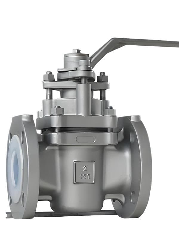
شیر مخروطی PFA
سایز: 1/2" - 12" (DN15 - DN300) فشار: Class 150 - 300 / PN 10-40 استاندارد: API 599، MSS SP-111 (با آستر پلاستیکی)، مخصوص تولیدکننده برای شیرهای پلاگ آستردار جنس بدنه: چدن داکتیل (GGG40) یا فولاد کربنی (A216 WCB) بدنه خارجی — آستر تمامبدنه PFA (پرفلوروآلکوکسی) پوششدهنده تمام سطوح در تماس با سیال نشیمنگاه: آستر PFA تا سطوح نشیمنگاه امتداد دارد — آببندی تماس PFA به PFA، بدون حلقههای نشیمنگاه فلزی جداگانه در معرض سیال فرآیند پلاگ: مخروطی یا استوانهای، چرخش 90 درجه، هسته فلزی با پوشش PFA روی سطح آببند طراحی: آستر تمامبدنه PFA بهصورت غلاف پیوسته، اتصالات فلنجی، پوشش بدنه پیچومهرهای، عملکرد بدون روانکننده چرا PFA روی شیر پلاگ — نه فقط "PTFE بهتر" شیرهای پلاگ مانند شیرهای توپی روی نشیمنگاه نمینشینند. شیر توپی حلقه نشیمنگاه خود را هنگام بسته شدن فشرده و هنگام باز شدن آزاد میکند — تماس عمدتاً نیروی عمودی است، با لغزش حداقلی. شیر پلاگ در هر سیکل، کل سطح آببند را روی نشیمنگاه بدنه میچرخاند. آن سطح پلاگ روی آستر میلغزد. بارها و بارها. این یک حرکت آببندی ذاتاً تهاجمیتر است. PTFE مدتی آن لغزش را تحمل میکند — سپس دچار جریان سرد میشود. ناحیه نشیمنگاه تحت تنش لغزشی مکرر نازک میشود. آستر PTFE در ناحیه تماس بهطور دائمی تغییر شکل میدهد، ضخامت خود را از دست میدهد، و در نهایت نمیتواند هندسه آببندی را حفظ کند. این را در کارخانههایی میبینید که شیرهای پلاگ با آستر PTFE در سرویس چرخهای کار میکنند: پس از چند صد عملگر، نشیمنگاه شروع به تراوش میکند. نه به این دلیل که شیمی به PTFE حمله کرده، بلکه به این دلیل که حرکت مکانیکی آن را فرسوده است. شیرهای پلاگ با آستر PFA دقیقاً همان حالت خرابی را برطرف میکنند. PFA تقریباً ده برابر کمتر از PTFE تحت بار مکانیکی خزش جریان سرد دارد. وقتی پلاگ میچرخد و آستر PFA را در نشیمنگاه فشرده میکند، PFA شکل خود را بازیابی میکند بهجای اینکه تغییر شکل یافته بماند. در طول صدها سیکل، ناحیه نشیمنگاه ضخامت و هندسه آببندی خود را حفظ میکند — این تفاوت واقعی عملیاتی است، نه فقط یک عدد آزمایشگاهی روی برگه مشخصات. عامل دوم: سطح قالبگیری ذوبی PFA صافتر از PTFE قالبگیری فشاری است. پلاگ روی سطح صافتری میلغزد — اصطکاک کمتر در هر سیکل، تولید حرارت کمتر، سایش مواد کمتر. دو مزیت مکانیکی که روی هم جمع میشوند: تغییر شکل کمتر در هر سیکل و اصطکاک کمتر در هر سیکل. به همین دلیل است که شیرهای پلاگ با آستر PFA نشیمنگاه خود را در سرویس خورنده چرخهای طولانیتر حفظ میکنند. هسته فلزی — جرمی که اهمیت دارد دوشاخه PFA خالص نیست. هسته فلزی دارد — چدن داکتیل یا فولاد ضدزنگ — با پوشش PFA روی سطح آببند. چرا فقط یک دوشاخه PFA توپُر قالبگیری نمیشود؟ چون دوشاخه برای نشستن با اقتدار به جرم نیاز دارد. در فشارهای خط پایین، یک دوشاخه PFA سبکوزن نیروی نشست کافی در برابر آستر تولید نمیکند. هسته فلزی وزن و صلبیت ساختاری را به دوشاخه میدهد تا آستر PFA را بهدرستی در محل نشست فشرده کند، در حالی که پوسته PFA هر ذره فلز را از سیال فرآیندی دور نگه میدارد. فرآیند هرگز با فلز تماس پیدا نمیکند. آستر هرگز کمبود فشار نشست ندارد. بدون گریس — بدون برنامه تعمیر و نگهداری شیرهای دوشاخهای روغنکاریشده نیاز به گریس دارند. پورتهای گریس، تفنگهای گریس، برنامه روغنکاری که کسی باید دنبال کند — و آن گریس باید با هر چیزی که در لوله جریان دارد سازگار باشد. در سرویس اسید غلیظ، پیدا کردن گریسی که تخریب یا آلوده نکند یک محدودیت واقعی است. شیرهای دوشاخهای با آستر PFA این را کاملاً حذف میکنند. ضریب اصطکاک پایین ذاتی PFA چرخش دوشاخه را خودروانکار میکند. بدون پورت تزریق گریس روی بدنه. بدون تفنگ گریس در انبار تعمیرات. بدون محاسبات سازگاری روانکننده. قطع جریان با چرخش یکچهارم، بدون روانکننده، در سرویس شیمیایی خورنده — این سادهسازی عملیاتی است. این شیر کجا در کارخانه شما جای میگیرد اسیدهای غلیظ — سولفوریک، هیدروکلریک، نیتریک. سرویس کلر. حلقههای سوزآور. حلالهای تهاجمی که در عرض چند هفته هر شیر فلزی بدون آستر را میخورند. هر کاربردی که به قطع جریان با چرخش یکچهارم نیاز دارید، جایی که بیشتر از گاهی اوقات چرخه میزنید، و جایی که شیرهای دوشاخهای با آستر PTFE قبلاً مشکلات سایش نشست را نشان دادهاند. این جایگاه خاص است: سیال خورنده، راحتی چرخش یکچهارم، دوام چرخهای بیشتر از آنچه PTFE میتواند ارائه دهد. اگر شیرهای دوشاخهای با آستر PTFE شما بعد از چند صد چرخه نشتی دارند، نسخه با آستر PFA ارتقایی است که ریشه مشکل را حل میکند — نه فقط شیمی، بلکه مکانیک نحوه آببندی واقعی یک شیر دوشاخهای. مقاومت در برابر جریان سرد. PTFE تحت تماس لغزشی مکرر در نشست دوشاخه بهطور دائمی تغییر شکل میدهد — جریان سرد پیدا میکند و نازک میشود. PFA شکل خود را تحت همان تنش مکانیکی بازیابی میکند. در سرویس چرخهای، این یعنی نشست PFA هندسه آببندی خود را در تعداد عمل بسیار بیشتری حفظ میکند. PFA همچنین سطح صافتری از قالبگیری مذاب دارد که اصطکاک لغزشی در هر چرخه را کاهش میدهد. بله. PFA و PTFE اساساً همان پروفایل مقاومت شیمیایی را دارند — هر دو اسیدهای غلیظ، کلر، سوزآورها و حلالهای تهاجمی را تحمل میکنند. مزیت PFA سازگاری شیمیایی گستردهتر نیست؛ دوام مکانیکی بهتر در شرایط تماس لغزشی خاصی است که شیرهای دوشاخهای ایجاد میکنند. نیروی نشست. دوشاخه به جرم کافی نیاز دارد تا آستر PFA را در ناحیه نشست با اقتدار مکانیکی فشرده کند، بهویژه در فشارهای خط پایین. یک دوشاخه PFA خالص برای تولید نیروی نشست کافی خیلی سبک است. هسته فلزی وزن و صلبیت را فراهم میکند — پوسته PFA روی سطح آببند فلز را از جریان فرآیندی جدا نگه میدارد. خیر. سطح...
مروری بر مشخصات فنی
شیرهای آسترکشی شده با فلورین، سیال فرآیندی خورنده را از بدنه فلزی از طریق یک آستر پلیمری فلوروکربنی ضخیم (۲-۵ میلیمتر) که تمام سطوح خیسشونده داخل حفره شیر را میپوشاند، جدا میکنند. بدنه بیرونی فلزی (چدن داکتیل، فولاد کربنی یا فولاد ضدزنگ) استحکام ساختاری و تحمل فشار را فراهم میکند — آستر پلیمری فلوروکربنی مقاومت شیمیایی را ایجاد میکند. این ساختار دو جداره دو عملکردی را که شیرهای فلزی استاندارد در یک ماده ترکیب میکنند، جدا میکند: تحمل فشار و مقاومت در برابر خوردگی. هیچ سطح فلزی با سیال فرآیندی تماس ندارد. صفر حمله خوردگی به بدنه، صفر آلودگی محیط فرآیندی توسط یونهای فلزی، صفر نگرانیهای گالوانیکی. FLOWKS پنج پیکربندی شیر آسترکشی شده با فلورین را با استفاده از سه ماده آستری تولید میکند. شیرهای توپی با آستر PTFE (پلیتترافلوئواتیلن) از یک غلاف PTFE تمامبدنه ۳-۵ میلیمتری استفاده میکنند که تمام سطوح داخلی را میپوشاند — PTFE از نظر شیمیایی تقریباً در برابر همه چیز بیاثر است بهجز فلزات قلیایی مذاب و فلوئور عنصری در دمای بالا، و آن را به آخرین سد خوردگی تبدیل میکند وقتی فولاد ضدزنگ، Hastelloy و تیتانیوم همگی شکست میخورند. شیرهای گلوب با آستر PFA (پرفلوئوروآلوکوکسی) از قابلیت فرآیندپذیری مذاب برتر PFA و خزش سرد ۱۰ برابر کمتر نسبت به PTFE استفاده میکنند — سطح قالبگیری شده صافتر و پایداری ابعادی بالاتر، هزاران سیکل گاز گرفتن دیسک-نشیمنگاه را تحمل میکنند جایی که PTFE نازک شده و نشتی میداد. شیرهای پروانهای با آستر PTFE جداسازی خوردگی را به قطرهای بزرگ (۲"-۲۴") در کلاس ۱۵۰ میآورند جایی که شیرهای توپی آستردار ۲-۳ برابر بیشتر هزینه داشتند. شیرهای یکطرفه با آستر FEP (اتیلن پروپیلن فلورینه) از سطح قالبگیری مذاب صافتر FEP برای دینامیک بهتر لولای دیسک و اصطکاک کمتر استفاده میکنند — همان مقاومت شیمیایی PTFE، رفتار مکانیکی بهتر برای عملکرد یکطرفه چرخشی/بالارونده. شیرهای یکطرفه عمودی توپی با آستر فلورین از یک توپ شناور آزاد بهعنوان تنها قطعه متحرک استفاده میکنند — بدون لولا، بدون فنر، بدون مکانیزم راهنما، بسته شدن گرانشی با یک توپ با کمترین حالتهای خرابی در سرویس یکطرفه خورنده.
شیرهای آسترکشی شده با فلورین FLOWKS جداسازی خوردگی بدون تماس فلزی را برای اسیدهای غلیظ، کلر، سود سوزآور، حلالها و تمام محیطهای فرآیندی که به فولاد ضدزنگ، Hastelloy و تیتانیوم حمله میکنند، فراهم میکنند. آسترهای ضخیم PTFE، PFA و FEP (۲-۵ میلیمتر) تمام سطوح خیسشونده داخل بدنه شیر را میپوشانند — پوسته بیرونی فلزی فشار را نگه میدارد در حالی که آستر پلیمری فلوروکربنی حمله شیمیایی را مسدود میکند. شیرهای توپی با آستر PTFE جداسازی خوردگی تمامبدنه را در سایز ۱/۲"-۱۲" کلاس ۱۵۰-۳۰۰ برای فرآوری شیمیایی و تولید دارویی ارائه میدهند جایی که فرآیند به هر فلز موجود حمله میکند. شیرهای گلوب با آستر PFA از خزش سرد ۱۰ برابر کمتر PFA و سطح قالبگیری مذاب صافتر برای سرویس گاز گرفتن استفاده میکنند — آستر هزاران سیکل دیسک-نشیمنگاه را تحمل میکند جایی که PTFE نازک شده و نشتی میداد. شیرهای پروانهای با آستر PTFE جداسازی پلیمری فلوروکربنی را به قطرهای بزرگ (۲"-۲۴") در کلاس ۱۵۰ با هزینه بهطور قابل توجهی کمتر نسبت به شیرهای توپی آستردار میآورند. شیرهای یکطرفه با آستر FEP پرداخت سطح صافتر FEP را برای دینامیک بهتر چرخش/بالا رفتن دیسک اعمال میکنند — همان مقاومت شیمیایی، اصطکاک کمتر، باز و بسته شدن قابل اعتمادتر. شیرهای یکطرفه عمودی توپی با آستر فلورین از یک توپ شناور آزاد بهعنوان تنها قطعه متحرک استفاده میکنند — بسته شدن گرانشی، صفر پیچیدگی مکانیکی، کمترین حالتهای خرابی برای سرویس یکطرفه عمودی خورنده.
دانلود محصولات
صنایع استفادهکننده از این محصول
کاربردها در بخشهای مختلف صنعتی.
Petrochemical
Corrosion-resistant valves for aggressive media in chemical processing plants. FLOWKS alloy and fluorine-lined valves are engineered to handle the most challenging petrochemical environments.
Chemical
Specialized alloy and fluorine-lined valves for highly corrosive and toxic chemical processes. Zero-emission bellows seal valves and exotic alloy construction for the chemical industry.
products.lookingMore
products.lookingMoreDesc
Ball Valves
FLOWKS offers floating ball valve, trunnion mounted ball valve and top entry ball valve for oil & gas, petrochemical and power generation. Designed per API 6D, API 608 and ASME B16.34.
DBB Valves
FLOWKS Double Block & Bleed (DBB) valves provide dual isolation with bleed verification in a single compact body. Replacing traditional multi-valve installations, FLOWKS DBB valves reduce weight, space and potential leak paths. Available in bolted bonnet, all-welded and expanding gate designs per API 6D and API 607.
Gate Valves
FLOWKS gate valves for isolation service in piping systems. Flexible wedge, solid wedge, slab and expanding gate designs per API 600, API 602 and ASME B16.34.
Globe Valves
FLOWKS globe valves for throttling and isolation. Standard, angle, Y-pattern and bellows seal configurations per API 602 and BS 1868.