Dải Sản Phẩm
Dòng sản phẩm van công nghiệp đầy đủ cho mọi ứng dụng.
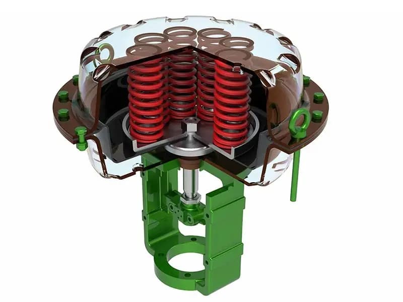
Cơ Cấu Khí Nén Màng
Hồi vị bằng lò xo (tác động đơn) hoặc tác động kép 100–10.000 lbf (diện tích màng × áp suất cấp) Tuyến tính, lên đến 4 inch (100mm) ISO 5211 (bề mặt lắp đặt) Mặt bích ISO 5211 đến thân van/nắp van; lắp trực tiếp trên van cầu, van cổng và van điều khiển Nitrile (NBR) / EPDM / Viton (FKM) / thép không gỉ Nhiều hộp lò xo; dải điều chỉnh bằng lựa chọn hộp lò xo; an toàn hỏng hóc đóng hoặc mở Tại sao bộ truyền động màng vận hành van điều khiển Đi qua bất kỳ đơn vị hóa dầu hoặc phòng điều khiển nhà máy điện nào — các van điều tiết lưu lượng trên đường ống quy trình gần như luôn được truyền động bằng màng. Không phải ngẫu nhiên. Van điều khiển cầu di chuyển nút van lên xuống. Đó là chuyển động tuyến tính. Bộ truyền động màng đẩy trục xuống (áp suất khí tác động lên đỉnh màng, nén lò xo, dẫn trục về phía đóng) và nhả trục lên (khí được loại bỏ, lò xo đẩy về phía mở). Chuyển động đẩy-kéo đó chính xác là những gì trục van cầu cần. Bản thân màng là bộ chuyển đổi áp suất thành lực. Một tấm cao su phẳng hoặc dạng sóng biến dạng khi khí đẩy vào một phía. Phép tính rất đơn giản — màng 100 inch vuông ở 60 psi cấp tạo lực đẩy 6.000 lbf. Vì diện tích màng lớn, bạn có được lực đẩy tương đương ở áp suất cấp thấp hơn. Không cần tăng khí lên trên 100+ psi như bộ truyền động piston yêu cầu. Khí dụng cụ tiêu chuẩn ở 40–80 psi đáp ứng được công việc. Yêu cầu áp suất thấp hơn đó quan trọng hơn hầu hết kỹ sư nhận ra. Hệ thống khí dụng cụ trong các nhà máy cũ chạy ở áp suất đầu ống góp 60 psi với bộ giảm áp cục bộ hạ xuống 40 psi tại van. Bộ truyền động màng hoạt động tốt ở áp suất đó. Bộ truyền động piston sẽ bị dừng. Hồi vị bằng lò xo nghĩa là bạn yên tâm Hành động an toàn hỏng hóc là lý do khác khiến bộ truyền động màng thống trị điều khiển quy trình. Nếu nguồn khí bị hỏng — máy nén ngừng, ống góp vỡ, đường cấp bị tắc — lò xo dẫn van về vị trí an toàn. Đóng cho chế độ đóng khi hỏng. Mở cho chế độ mở khi hỏng. Lò xo không phụ thuộc vào khí, điện hoặc bất kỳ nguồn năng lượng bên ngoài nào. Nó chỉ là lực cơ học tích trữ được giải phóng. Trọng lực và lò xo luôn sẵn có. Trên đường ống hơi 400-psig, bạn muốn van điều khiển đó đóng khi mất khí. Lò xo làm điều đó. Không cần pin dự phòng. Không cần bình khí phụ. Chỉ cần một lò xo nén bên trong vỏ bộ truyền động đẩy trục về vị trí an toàn. Độ tin cậy đó là lý do bộ truyền động màng nằm trên mọi van điều khiển quan trọng trong ứng dụng hóa dầu và điện. Vật liệu màng phù hợp với dịch vụ Nitrile xử lý dịch vụ dầu khí thông thường. EPDM chịu được hơi nước và nước nóng — thường dùng trên van điều khiển nước cấp lò hơi. Viton chống ăn mòn hóa học trên các đường axit và dung môi. Khi chất lỏng quá trình ăn mòn mạnh đến mức cả Viton cũng bị phân hủy, màng thép không gỉ sẽ thay thế. Chọn dựa trên những gì bên trong thân van, không phải thứ trông rẻ nhất trong catalog. Biết Giới Hạn Hành Trình Bộ truyền động màng tiêu chuẩn cung cấp hành trình tuyến tính tối đa 4 inch. Vượt quá đó, màng biến dạng quá xa và mất diện tích hiệu dụng — lực đẩy giảm. Thiết kế màng nhiều tầng kéo dài hành trình, nhưng bạn đánh đổi lực đẩy để lấy quãng đường di chuyển. Nếu van cổng của bạn cần hành trình thân van 6 inch, bạn cần xi lanh piston, không phải bộ truyền động màng. A: Không trực tiếp. Bộ truyền động màng tạo lực đẩy tuyến tính, không phải mô-men xoay. Bạn cần giá đỡ và liên kết để chuyển đổi chuyển động tuyến tính thành xoay 90° — và việc chuyển đổi đó thêm phức tạp và mất chuyển động. Đối với van xoay 1/4 vòng, hãy dùng bộ truyền động rack-and-pinion hoặc scotch yoke. A: Màng biến dạng và diện tích áp suất hiệu dụng của nó thu hẹp khi hành trình tăng. Màng ở độ biến dạng 4 inch có diện tích làm việc nhỏ hơn ở 1 inch. Thiết kế nhiều tầng bù đắp phần nào, nhưng sự đánh đổi giữa chiều dài hành trình và lực đẩy đầu ra là cơ bản của hình học màng. A: Thay hộp lò xo. Các bộ lò xo khác nhau tạo ra lực an toàn khi mất nguồn khác nhau. Vỏ bộ truyền động chứa nhiều lò xo — bạn thay bộ lò xo để khớp với lực đóng mà van của bạn yêu cầu. Không cần thay toàn bộ bộ truyền động. A: 60 psi là điểm tối ưu cho hầu hết các lắp đặt. Nó cung cấp lực đẩy đầy đủ ở kích thước màng tiêu chuẩn và khớp với áp suất ống khí dụng cụ điển hình. Nếu hệ thống khí của bạn chạy thấp hơn — 40 psi ở các nhà máy cũ — hãy chỉ định kích thước màng lớn hơn để bù đắp. A: Trong dịch vụ điều khiển điều biến. Bộ truyền động màng có ma sát làm kín không đáng kể, nghĩa là độ trễ thấp hơn và độ chính xác vị trí tốt hơn. Màng uốn cong tự do; vòng chữ O của piston kéo lê trên thành xi lanh. Sự khác biệt ma sát đó quan trọng khi bạn đang tiết lưu ở độ mở 30% và bộ định vị đang thực hiện các điều chỉnh nhỏ.
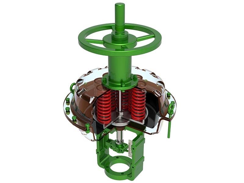
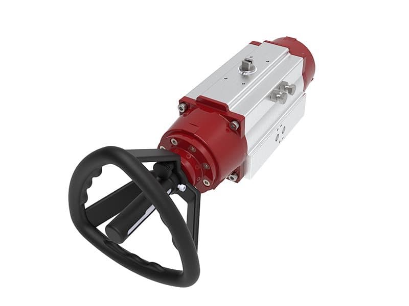
Cơ Cấu Khí Nén Màng Có Tay Quay
Hồi lò xo (tác động đơn) hoặc tác động kép 100–10.000 lbf (diện tích màng × áp suất cấp) Tuyến tính, tối đa 4 inch (100mm) ISO 5211 (bề mặt lắp đặt) Mặt bích ISO 5211 đến nắp van/đế; tay quay ở bên cạnh hoặc trên đỉnh đế bộ truyền động Nitrile (NBR) / EPDM / Viton (FKM) / thép không gỉ Nhiều hộp lò xo; dải điều chỉnh bằng cách chọn hộp lò xo Điều khiển tay phụ có ly hợp; ly hợp gài tay quay vào thân van khi xoay, nhả ra khi bộ truyền động tiếp tục điều khiển khí nén Tay Quay Là Kế Hoạch Dự Phòng Của Bạn Cùng bộ truyền động màng. Cùng lực đẩy đầu ra. Cùng hồi lò xo an toàn khi mất nguồn. Tay quay thêm một thứ — điều khiển tay thay thế khi không có khí. Nghe có vẻ đơn giản, và về mặt cơ khí thì đúng vậy. Nhưng các tình huống vận hành mà nó quan trọng thì đáng để hiểu rõ. Khởi động nhà máy. Hệ thống khí nén mất nhiều ngày để đưa vào vận hành. Dao động áp suất, rò rỉ hệ thống, sự cố máy nén — ống khí dụng cụ chưa ổn định. Người vận hành cần định vị van điều khiển bằng tay cho đến khi hệ thống khí ổn định. Tay quay cho phép họ làm điều đó. Xoay vô lăng, ly hợp gài, thân van phản hồi. Không cần khí. Sự cố nguồn khí giữa quá trình chạy. Máy nén ngừng. Ống khí bị vỡ. Đường cấp đến một van cụ thể bị tắc. Hồi lò xo đẩy van về vị trí an toàn — mở hoàn toàn hoặc đóng hoàn toàn. Điều đó bảo vệ khỏi nguy cơ quá trình. Nhưng nếu quá trình có thể tiếp tục chạy ở tốc độ giảm trong thời gian mất nguồn thì sao? Mở hoàn toàn hoặc đóng hoàn toàn có thể quá mạnh. Tay quay cho phép bạn đặt van ở độ mở 30%, tiếp tục sản xuất ở công suất giảm, và chờ hệ thống khí quay lại. Cơ Chế Ly Hợp Hoạt Động Như Thế Nào Tay quay không chống lại bộ truyền động trong vận hành bình thường. Đó là thiết kế có ly hợp. Khi điều khiển khí nén hoạt động, ly hợp nhả tay quay khỏi thân van — tay quay xoay tự do, và thân van chỉ phản hồi theo lực đẩy của bộ truyền động. Khi bạn xoay tay quay, ly hợp gài và vô lăng dẫn động thân van trực tiếp. Khi bộ truyền động tiếp quản lại, ly hợp tự nhả ra. Không cần nhả thủ công. Cơ chế tự xử lý. Tính năng tự nhả đó ngăn ngừa một lỗi phổ biến tại hiện trường — người vận hành để tay quay gài sau khi điều khiển tay, khiến bộ truyền động chống lại vị trí tay quay trong vận hành bình thường. Thiết kế có ly hợp loại bỏ vấn đề đó. Khi Nào Chỉ Định Tùy Chọn Tay Quay Thêm tay quay trên các van điều khiển phục vụ chức năng quá trình quan trọng — điều khiển nước cấp trên lò hơi, điều khiển nhiệt độ lò phản ứng, van tiết lưu đường ống chính. Bất kỳ van nào mà tiếp tục vận hành ở công suất giảm khi mất khí tốt hơn là dừng hoàn toàn. Cũng áp dụng cho van ở vị trí xa xôi nơi việc bảo trì hệ thống khí mất nhiều giờ — giàn ngoài khơi, giếng xa, trạm đường ống phân tán. Tay quay cho người vận hành điều khiển tại chỗ bất kể tình trạng nguồn khí. Tay quay thêm chi phí và trọng lượng. Nó chiếm không gian trên đế. Trên các van dịch vụ không quan trọng nơi dừng hoàn toàn khi mất khí có thể chấp nhận được, hãy bỏ qua. Nhưng trên các van giữ nhà máy hoạt động, tùy chọn tay quay là bảo hiểm rẻ so với việc dừng máy ngoài kế hoạch. A: Vâng, khi bạn gài nó. Vô lăng dẫn động trục van đến bất kỳ vị trí nào bạn đặt — bao gồm cả các vị trí trung gian mà lò xo không thể đạt tới. Khi bạn nhả vô lăng và nguồn khí vẫn không có, lò xo sẽ đẩy van trở về vị trí an toàn khi mất khí. A: Về mặt cơ khí là có, nhưng bạn không nên làm vậy. Bộ truyền động đang điều khiển vị trí van dựa trên tín hiệu quá trình. Việc can thiệp thủ công vào vị trí đó sẽ phá vỡ vòng điều khiển. Chỉ sử dụng vô lăng trong thời gian mất nguồn khí hoặc bảo trì. A: Lắp bên hông trên giá đỡ bộ truyền động là tiêu chuẩn — nó giữ chiều cao tổng thể thấp và phù hợp với các lắp đặt thẳng đứng chật hẹp. Lắp trên đỉnh có sẵn khi khoảng trống bên hông bị hạn chế. Vị trí lắp đặt phụ thuộc vào loại van và bố trí giá đỡ đường ống. A: Nó làm tăng trọng lượng của cụm bộ truyền động — vô lăng, cơ cấu ly hợp và liên kết cơ khí. Trên các bộ truyền động cỡ nhỏ (diện tích màng dưới 50 inch vuông), việc tăng trọng lượng là đáng kể. Trên các bộ truyền động lớn hơn, trọng lượng vô lăng tương đối nhỏ. Kiểm tra tổng trọng lượng cụm lắp ráp so với khả năng chịu tải của thân van. A: Có. Bộ truyền động màng tác động kép không có lò xo hồi vị, vì vậy khi mất khí, van giữ nguyên vị trí cuối cùng. Vô lăng cung cấp khả năng định vị thủ công trong thời gian mất khí — cùng chức năng, cùng cơ cấu nhả ly hợp. Vô lăng được cho là quan trọng hơn trên bộ truyền động tác động kép vì không có lò xo an toàn để dựa vào.
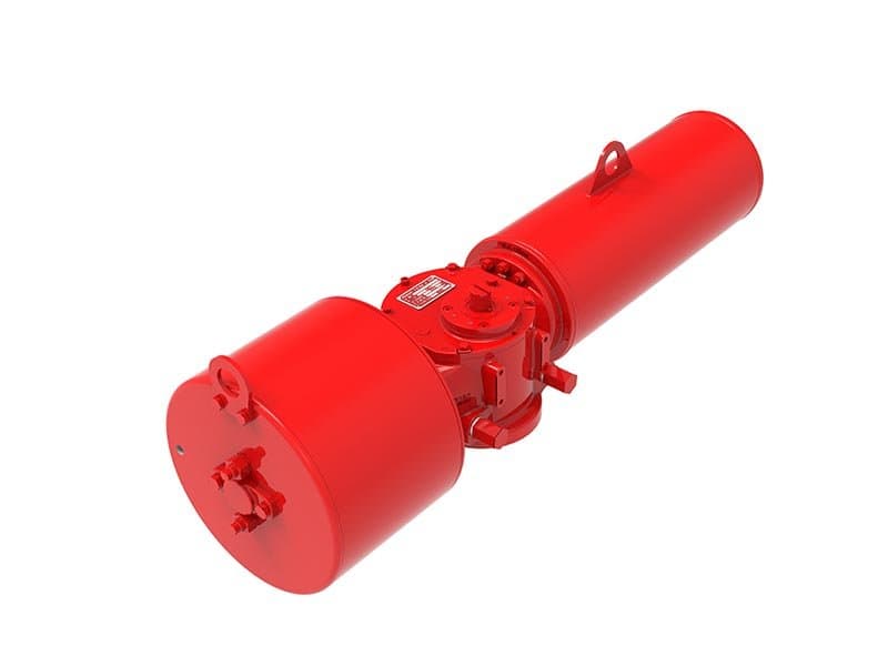
Cơ Cấu Khí Nén Scotch Yoke
Hồi vị bằng lò xo (tác động đơn) hoặc tác động kép 500–100.000 Nm trên các cỡ model Chuyển động quay 90° ISO 5211 (lắp đặt), NAMUR (lắp đặt solenoid) Xi lanh đơn, piston kép; cơ cấu scotch yoke chuyển đổi chuyển động tuyến tính của piston thành chuyển động quay 90° Hộp lò xo trong xi lanh (model hồi vị bằng lò xo); nhiều bộ lò xo có sẵn; hoặc tác động kép không có lò xo Mặt bích ISO 5211 kết nối trực tiếp với thân van hoặc giá đỡ; giao diện NAMUR cho solenoid và phụ kiện Mô-men Xoắn Biến Thiên Là Lợi Thế Thực Sự Của Scotch Yoke Bộ truyền động rack-and-pinion tạo ra mô-men xoắn không đổi trên hành trình 90°. Bộ truyền động scotch yoke tạo ra mô-men xoắn biến thiên — và chính sự biến thiên đó là lý do chúng tồn tại. Van góc phần tư cần nhiều mô-men xoắn hơn để mở bi hoặc đĩa khỏi vị trí đóng so với duy trì chuyển động quay. Mô-men xoắn mở ban đầu tại vị trí đóng vượt mô-men xoắn vận hành tại giữa hành trình từ 30–50% trên các van bướm và van bi điển hình. Trên các van lớn, áp suất cao, chênh lệch đó càng lớn hơn. Một van bi 24 inch Class 300 có thể cần 15.000 Nm để mở khỏi đế van nhưng chỉ cần 8.000 Nm mô-men xoắn vận hành tại giữa hành trình. Hình học scotch yoke giải quyết vấn đề này. Tay đòn yoke chuyển đổi lực piston thành mô-men quay — và tỷ lệ chuyển đổi này thay đổi trên hành trình. Tại vị trí mở ban đầu (0–10° quay), hình học tay đòn yoke tạo ra hệ số nhân mô-men xoắn cao hơn. Lực piston được khuếch đại thành lực quay lớn hơn tại đầu hành trình, chính xác nơi van cần nhất. Tại giữa hành trình, hệ số nhân giảm xuống, phù hợp với yêu cầu mô-men xoắn vận hành thấp hơn. Đường cong mô-men xoắn khớp với đường cong nhu cầu mô-men xoắn của van. Bộ Truyền Động Nhỏ Hơn Trên Van Lớn Vì scotch yoke cung cấp mô-men xoắn mở ban đầu cao hơn trên mỗi đơn vị nguồn khí, bạn có thể chỉ định bộ truyền động nhỏ hơn cho cùng một van. Hoặc chạy áp suất cấp thấp hơn. Hoặc cả hai. Trên van bướm 36 inch trong dịch vụ nước, bộ truyền động scotch yoke ở 80 psi có thể tạo ra mô-men xoắn mở đầy đủ trong khi bộ truyền động rack-and-pinion cần 100 psi để cung cấp cùng lực ban đầu. Sự khác biệt áp suất này quan trọng tại các nhà máy nơi ống góp khí dụng cụ chạy ở 80 psi và việc tăng lên 100 psi yêu cầu bộ tăng áp chuyên dụng tại mỗi van. Chuyển Động Mượt Hơn Kéo Dài Tuổi Thọ Đế Van Bộ truyền động rack-and-pinion tác dụng lực đột ngột khi van bật khỏi đế. Đầu ra mô-men xoắn không đổi có nghĩa là bộ truyền động cung cấp mô-men xoắn tối đa ngay khi van bắt đầu chuyển động — sốc cơ học đập vào đế van mỗi chu kỳ. Scotch yoke khởi động chậm. Gia tốc piston tăng dần qua giữa hành trình. Đĩa van nâng khỏi đế từ từ thay vì bật ra đột ngột. Trên các van góc phần tư lớn, áp suất cao, chuyển động mở mượt hơn đó giảm lực va đập lên vòng đế. Tuổi thọ đế van kéo dài. Chu kỳ bảo trì giãn ra. Trên các van chu kỳ hoạt động thường xuyên — van cách ly tự động trong quy trình mẻ — sự khác biệt tuổi thọ đế van tích lũy qua hàng nghìn chu kỳ. Chỉ Định Scotch Yoke Khi Nhu Cầu Mô-men Xoắn Cao Bộ truyền động scotch yoke là lựa chọn đúng đắn trên các van góc phần tư lớn (van bướm 8–48 inch, van bi 8–24 inch) nơi mô-men xoắn đóng vượt quá những gì rack-and-pinion cung cấp ở áp suất cấp hợp lý. Trên các van nhỏ hơn nơi yêu cầu mô-men xoắn ở mức trung bình, rack-and-pinion đơn giản và rẻ hơn. Đừng chỉ định quá mức — sự phức tạp và chi phí của scotch yoke chỉ hợp lý khi đặc tính mô-men xoắn biến thiên giải quyết được vấn đề thực tế. A: Chi phí và độ phức tạp. Cơ cấu scotch yoke có nhiều bộ phận chuyển động hơn rack-and-pinion — tay đòn yoke, rãnh và chốt làm tăng chi phí gia công và lắp ráp. Trên các van nơi mô-men xoắn không đổi là đủ, rack-and-pinion hoàn thành công việc với chi phí thấp hơn. Scotch yoke xứng đáng với mức giá cao hơn trên các van lớn có mô-men xoắn mở ban đầu cao. A: Nó thay đổi phương pháp tính kích thước. Bạn tính kích thước dựa trên mô-men xoắn mở ban đầu tại đầu hành trình, không phải mô-men xoắn không đổi. Tính toán yêu cầu mô-men xoắn đóng/mở của van, sau đó xác minh rằng mô-men xoắn của scotch yoke tại vị trí mở vượt quá yêu cầu đó với biên độ an toàn của bạn. Đường cong mô-men xoắn được công bố trong bảng dữ liệu của nhà sản xuất cho từng cỡ model. A: 80 psi là điển hình. Cao hơn so với bộ truyền động màng vì đường kính piston nhỏ hơn diện tích màng. Bộ truyền động kiểu scotch yoke chịu được tới 120 psi trên các mẫu mô-men cao — vòng đệm piston xử lý được áp suất. Nếu đường ống khí của nhà máy chạy ở 60 psi, hãy chỉ định kích thước bộ truyền động lớn hơn để bù đắp. A: Chúng có thể, nhưng không lý tưởng cho việc tiết lưu chính xác. Mô-men đầu ra thay đổi có nghĩa là bộ định vị thấy các điều kiện lực khác nhau ở các góc trục khác nhau. Đối với van góc phần tư điều biến, mô-men không đổi của rack-and-pinion cho phản hồi bộ định vị dễ dự đoán hơn. Scotch yoke tỏa sáng trong van đóng/mở và cách ly dịch vụ khắc nghiệt. A:...
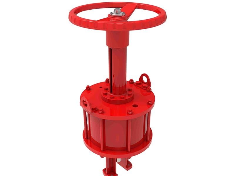
Xi-lanh Hành Trình Tuyến Tính
Lò xo hồi vị (tác động đơn) hoặc tác động kép 500–50.000 lbf (diện tích lỗ × áp suất cấp) 40–150 psi (3–10 bar) 1–12 inch (25–300mm) tuyến tính ISO 5211 (bề mặt lắp đặt) Piston tác động kép trong thân xi lanh; vòng đệm O-ring hoặc vòng đệm môi; áp suất khí dẫn động piston theo cả hai hướng Hộp lò xo bên trong (mẫu lò xo hồi vị); phạm vi điều chỉnh bằng cách chọn hộp lò xo Mặt bích ISO 5211 hoặc khớp chữ U; giá đỡ trên yoke van; kết nối trục trực tiếp qua đai ốc nối hoặc kết nối yoke Sức Mạnh Piston Nơi Màng Yếu Kém Xi lanh hành trình thẳng phục vụ cùng loại van như bộ truyền động màng — van cầu, van cổng, van điều khiển cần lực đẩy tuyến tính. Nhưng chúng giải quyết hai vấn đề mà bộ truyền động màng không thể. Lực đẩy cao hơn trong kích thước nhỏ hơn. Lỗ xi lanh thay thế diện tích màng. Đường kính lỗ nhỏ hơn màng để có lực đẩy tương đương, vì xi lanh piston chịu được áp suất cấp cao hơn — lên tới 150 psi so với 80 psi của màng. Áp suất cao hơn × diện tích nhỏ hơn = cùng lực đẩy với kích thước bộ truyền động nhỏ gọn hơn. Trên các lắp đặt thẳng đứng và giá đỡ ống chật hẹp nơi bộ truyền động màng không vừa giữa các đường ống liền kề, xi lanh piston lắp vào và cung cấp lực bạn cần. Hành trình dài hơn mà không làm giảm lực đẩy. Bộ truyền động màng ngăn đạt tối đa khoảng 4 inch vì màng ngăn bị biến dạng và mất diện tích hiệu dụng khi hành trình dài hơn. Xi lanh piston chỉ kéo dài thân van. Hành trình 6, 8, 12 inch là tiêu chuẩn cho van cổng có hành trình trục dài, và vòng đệm O-ring vẫn hiệu quả ở bất kỳ vị trí nào dọc theo lỗ khoan. Lực đẩy không giảm theo chiều dài hành trình — diện tích piston không đổi cho dù piston nằm ở vị trí cách nắp cuối 1 inch hay 10 inch. Sự nhất quán đó rất quan trọng đối với van cổng, nơi việc mở hoàn toàn yêu cầu kéo dài trục van và lực đóng khi đóng hoàn toàn phải khớp với lực mở khi mở hoàn toàn. Sự Đánh Đổi Ma Sát Xi lanh piston trả giá cho kích thước nhỏ gọn bằng ma sát vòng đệm. Vòng đệm O-ring trên piston ma sát với bề mặt lỗ xi lanh. Lực ma sát đó làm giảm lực đẩy thực tại trục van — bạn cần áp suất cấp cao hơn để cung cấp cùng lực hiệu dụng mà bộ truyền động màng tạo ra ở áp suất thấp hơn. Trên van đóng/mở nơi trục di chuyển toàn hành trình mỗi chu kỳ, mất mát ma sát đó có thể chấp nhận được. Van đóng hoặc mở bất kể vài trăm pound ma sát. Trên van điều khiển điều biến, ma sát tạo ra vấn đề khác — độ trễ. Bộ định vị ra lệnh điều chỉnh nhỏ, ví dụ 2% hành trình trục. Ma sát hấp thụ lực điều chỉnh trước khi trục di chuyển. Bộ định vị vượt quá ở lần điều chỉnh tiếp theo. Trục dao động quanh vị trí mục tiêu. Hiệu suất vòng điều khiển suy giảm. Van dao động. Biến quá trình dao động. Bộ truyền động màng có ma sát vòng đệm không đáng kể. Màng uốn tự do — không có lực kéo O-ring chống lại bề mặt lỗ. Đối với dịch vụ điều biến nơi định vị chính xác quan trọng, bộ truyền động màng mang lại độ chính xác vị trí tốt hơn và phản hồi vòng điều khiển mượt mà hơn. Chọn Dựa Trên Ứng Dụng Sử dụng xi lanh piston cho van cổng có yêu cầu hành trình dài, trên các lắp đặt nơi không gian không đủ cho bộ truyền động màng, và cho dịch vụ đóng/mở nơi độ trễ không ảnh hưởng đến hiệu suất. Sử dụng bộ truyền động màng cho van điều khiển điều biến nơi độ chính xác vị trí là ưu tiên. Hai loại bộ truyền động chồng lấn trên cùng loại van nhưng phục vụ nhu cầu vận hành khác nhau. A: Khi hành trình vượt quá 4 inch, khi không gian lắp đặt không đủ cho bộ truyền động màng, hoặc khi áp suất cấp trên 80 psi có sẵn và bạn muốn kích thước bộ truyền động nhỏ gọn. Van cổng có hành trình trục 6+ inch là ứng dụng xi lanh phổ biến nhất. A: Không, trong phạm vi định mức. Vòng đệm O-ring piston xử lý 150 psi mà không có vấn đề mỏi. Lỗ xi lanh và nắp cuối được định mức cho áp suất cấp tối đa. Bộ truyền động màng không chịu được áp suất đó vì vật liệu màng mỏi dưới biến dạng áp suất cao lặp lại — vòng đệm piston không biến dạng, nó trượt. A: Phụ thuộc vào đường kính lỗ, loại vòng đệm và tình trạng xi lanh. Vòng đệm O-ring trên xi lanh tiêu chuẩn tạo lực ma sát 50–200 lbf tùy thuộc kích thước lỗ. Vòng đệm môi giảm xuống 20–80 lbf nhưng đắt hơn. Trên lực đẩy đầu ra 5.000 lbf, lực ma sát đó là 1–4% — chấp nhận được cho dịch vụ đóng/mở. Trên lực đẩy đầu ra 500 lbf cho van điều khiển nhỏ, cùng tỷ lệ ma sát đó trở nên đáng kể. A: Bạn có thể, và nhiều nhà máy làm vậy. Nhưng kỳ vọng độ trễ cao hơn bộ truyền động màng. Bộ định vị có phản hồi có thể bù đắp phần nào, nhưng dải chết giữa vị trí lệnh và vị trí thực tế sẽ rộng hơn. Nếu dung sai vòng điều khiển chặt, hãy chỉ định bộ truyền động màng thay thế. A: Khớp hành trình xy lanh với hành trình trục van theo định mức. Van cầu thường cần 1–3 inch. Van cổng cần 4–12 inch tùy thuộc vào kích thước van và cấp áp suất. Bảng dữ liệu van của nhà sản xuất liệt kê hành trình trục — hãy mua hành trình xy lanh khớp với nó, không dài hơn. Hành trình thừa làm tăng chiều dài xy...
Xi-lanh Dòng AT
Tác động kép (tiêu chuẩn) hoặc hồi lò xo (có hộp lò xo) 10–5.000 Nm (các cỡ model AT05 đến AT350) 40–80 psi (2,5–6 bar) Xoay 90° góc phần tư ISO 5211 (lắp đặt), NAMUR (solenoid/phụ kiện) Hai piston đối nghịch dẫn động bánh răng thanh răng; bánh răng trung tâm tạo ra chuyển động xoay đầu ra 90°; mô-men xoắn không đổi suốt toàn hành trình Hộp lò xo phía sau mỗi piston (model hồi lò xo); định vị an toàn khi mất khí Thân nhôm đùn; bề mặt khoan được anod hóa cứng; nắp cuối bắt bu lông hoặc ren; nhỏ gọn và trọng lượng nhẹ Thiết Bị Truyền Động Mặc Định Cho Van Góc Phần Tư Dòng AT là lựa chọn khi van bướm hoặc van bi cần tự động hóa ở kích thước trung bình. Van bướm nước lạnh HVAC. Van bi điều khiển lưu lượng xử lý nước. Cách ly tiện ích quy trình tổng hợp. Dòng AT xử lý tất cả — nhỏ gọn, nhẹ, giá phải chăng, và đủ tiêu chuẩn hóa để mọi nhà sản xuất phụ kiện đều chế tạo phần cứng lắp NAMUR cho nó. Cơ chế thanh răng-bánh răng là lõi. Hai piston trong một thân xy lanh. Mỗi piston dẫn động một bánh răng thanh răng. Các thanh răng ăn khớp với bánh răng trung tâm. Khí đẩy cả hai piston về phía trung tâm, các thanh răng xoay bánh răng trung tâm 90°. Mô-men xoắn không đổi suốt toàn hành trình — hình học thanh răng-bánh răng tạo ra lực xoay đồng đều bất kể vị trí bánh răng trung tâm. Đầu ra không đổi đó đơn giản hóa việc chọn kích thước. Bạn chọn model cung cấp mô-men xoắn trên yêu cầu đóng van của mình, thêm biên độ an toàn, và xong. Không cần phân tích đường cong mô-men, không cần tính toán vị trí mở ban đầu, không có đầu ra biến đổi cần tính đến. Nhôm Giữ Trọng Lượng Thấp Thân nhôm đùn nhẹ hơn vỏ scotch yoke gang hoặc thép từ 40–60%. Trên van bướm 12 inch lắp giữa mặt bích, trọng lượng thiết bị truyền động quan trọng — thiết bị truyền động nặng đặt công xôn trên thân van có thể làm biến dạng kết nối mặt bích theo thời gian. Dòng AT giữ tổng trọng lượng cụm lắp ráp trong phạm vi mà thân van và giá đỡ đường ống xử lý được mà không cần gia cố thêm. Bề mặt khoan anod hóa cứng bảo vệ bên trong xy lanh mà không thêm trọng lượng. Vòng chữ O piston chạy trên bề mặt anod hóa với ma sát thấp và tuổi thọ gioăng dài. Vỏ nhôm ăn mòn ít hơn thép sơn trong môi trường ẩm và ăn mòn nhẹ — nhà máy xử lý nước, lắp đặt ven biển, thiết bị HVAC ngoài trời. Đối với môi trường hóa chất khắc nghiệt, chỉ định lớp phủ tùy chọn hoặc biến thể thép không gỉ. NAMUR Nghĩa Là Không Cần Khung Đỡ Tùy Chỉnh Giao diện NAMUR trên thân thiết bị truyền động cho phép lắp trực tiếp van solenoid, công tắc giới hạn, và bộ định vị. Mẫu bu lông và vị trí kênh khí được tiêu chuẩn hóa. Không cần khung đỡ tùy chỉnh, không cần tấm chuyển đổi, không cần khoan lỗ trên vỏ thiết bị truyền động để lắp phụ kiện không tiêu chuẩn. Mọi nhà sản xuất phụ kiện lớn đều chế tạo sản phẩm tương thích NAMUR. Tính thay thế lẫn nhau đó giảm độ phức tạp mua sắm và tồn kho bảo trì — một thiết kế van solenoid phù hợp với mọi thiết bị truyền động dòng AT trong nhà máy. Nơi Dòng AT Dừng Lại Và Scotch Yoke Bắt Đầu Dòng AT bao phủ mô-men xoắn lên đến 5.000 Nm. Điều đó đủ cho van bướm lên đến khoảng 12 inch và van bi lên đến khoảng 8 inch trong dịch vụ áp suất trung bình. Vượt quá kích thước và áp suất đó, mô-men xoắn đóng vượt quá những gì dòng AT cung cấp ở áp suất cấp tiêu chuẩn. Scotch yoke tiếp quản — đầu ra mô-men xoắn biến đổi của nó tạo ra lực mở ban đầu cao hơn cho van lớn. Đừng kéo dãn dòng AT vượt quá phạm vi của nó. Thiết bị truyền động dừng trên van mô-men cao, và bạn quay lại vận hành thủ công. A: Dòng AT cho van góc phần tư kích thước trung bình nơi mô-men xoắn dưới 5.000 Nm và chênh lệch đóng/mở không quá lớn. Scotch yoke cho van lớn (van bướm 12+ inch, van bi 8+ inch) có mô-men mở ban đầu cao. Nếu bảng dữ liệu van của bạn cho thấy mô-men đóng vượt quá mức tối đa của dòng AT cho áp suất cấp của bạn, bạn cần scotch yoke. A: Sự đơn giản. Bạn chọn kích thước cho một giá trị mô-men xoắn. Bộ định vị thấy điều kiện lực nhất quán ở mọi góc trục. Đáp ứng điều khiển điều biến có thể dự đoán. Không cần phân tích đường cong mô-men. Đối với hầu hết ứng dụng góc phần tư ở kích thước trung bình, mô-men xoắn không đổi là tất cả những gì bạn cần. A: Có, với lớp hoàn thiện anod hóa cứng tiêu chuẩn. Anod hóa nhôm chống tia UV, độ ẩm, và ăn mòn nhẹ. Trong môi trường ven biển không khí mặn hoặc khí quyển nhà máy hóa chất có hơi axit, chỉ định lớp phủ epoxy tùy chọn hoặc biến thể thép không gỉ. Đừng giả định nhôm trần chịu được tiếp xúc khắc nghiệt. A: Có. Đầu ra mô-men xoắn không đổi cho bộ định vị điều kiện lực nhất quán, đơn giản hóa việc hiệu chỉnh và cải thiện độ ổn định vòng điều khiển. Kết hợp dòng AT với bộ định vị khí nén hoặc điện-khí nén lắp NAMUR cho dịch vụ tiết lưu. Cụm phụ kiện nhỏ gọn giữ tổng thể lắp ráp gọn gàng. A: Hộp lò xo nằm phía sau mỗi piston bên trong thân xy lanh. Khi nguồn khí bị loại bỏ, lò xo đẩy piston ra khỏi trung tâm, xoay bánh răng trung tâm đến...
Tổng quan kỹ thuật
Bộ truyền động khí nén chuyển đổi năng lượng khí nén thành chuyển động của van — lực đẩy tuyến tính cho van cầu, van cổng và van điều khiển, hoặc mô-men xoắn quay cho van bi, van bướm và van cắm. Loại bộ truyền động phù hợp với loại chuyển động của van: bộ truyền động tuyến tính đẩy trục van lên xuống, bộ truyền động quay xoay trục van 90°. FLOWKS sản xuất năm cấu hình bộ truyền động khí nén bao phủ cả hai loại chuyển động và ba cơ chế tạo lực. Bộ truyền động khí nén màng tạo lực đẩy tuyến tính thông qua màng linh hoạt biến dạng dưới áp suất khí — áp suất cấp thấp (40-80 psi), diện tích màng lớn bù cho áp suất thấp hơn, an toàn hỏng hóc bằng lò xo hồi vị, và là bộ truyền động tiêu chuẩn cho van điều khiển quy trình nơi độ trễ thấp và định vị trục chính xác là quan trọng. Bộ truyền động khí nén màng có tay quay bổ sung bộ điều khiển tay thủ công có thể ngắt ly hợp để khởi động nhà máy và vận hành khi mất nguồn khí — hiệu suất bộ truyền động tương tự, cộng thêm khả năng định vị bằng tay quay khi không có khí. Bộ truyền động khí nén kiểu ách bò (scotch yoke) tạo mô-men xoắn quay biến đổi thông qua cơ chế ách dẫn động bằng piston — mô-men xoắn đạt đỉnh tại vị trí mở ban đầu để nhả van xoay 1/4 vòng, và hình học tạo mô-men xoắn cao hơn ở kích thước van lớn (van bướm 8"-48", van bi 8"-24") nơi bộ truyền động thanh răng-pinion không thể tạo đủ lực. Xi lanh hành trình tuyến tính sử dụng thiết kế piston trong xi lanh để tạo lực đẩy tuyến tính — áp suất cấp cao hơn (lên đến 150 psi), khả năng hành trình dài hơn (lên đến 12"), nhỏ gọn hơn bộ truyền động màng ở lực đẩy tương đương, được chỉ định cho van cổng có hành trình trục dài và không gian lắp đặt hẹp. Xi lanh dòng AT là bộ truyền động quay thanh răng-pinion trong thân nhôm đùn — mô-men xoắn không đổi trên hành trình 90°, lắp phụ kiện NAMUR, nhỏ gọn và nhẹ cho tự động hóa van xoay 1/4 vòng cỡ nhỏ đến trung bình lên đến van bướm 12" và van bi 8".
Bộ truyền động khí nén FLOWKS tự động hóa vận hành van trên cả hai loại van hành trình tuyến tính và van xoay 1/4 vòng. Bộ truyền động khí nén màng tạo lực đẩy tuyến tính cho van cầu, van cổng và van điều khiển — áp suất cấp thấp, an toàn hỏng hóc bằng lò xo hồi vị, độ trễ thấp cho điều khiển điều chỉnh chính xác, dải lực đẩy 100-10.000 lbf. Bộ truyền động khí nén màng có tay quay bổ sung bộ điều khiển tay thủ công có thể ngắt ly hợp để khởi động và vận hành khi mất nguồn khí — cùng bộ truyền động cộng thêm khả năng định vị thủ công khi khí nén không khả dụng. Bộ truyền động khí nén kiểu ách bò (scotch yoke) tạo mô-men xoắn quay biến đổi cho van xoay 1/4 vòng cỡ lớn — mô-men xoắn đạt đỉnh tại vị trí mở ban đầu để nhả van bi và van bướm đáng tin cậy, dải đầu ra 500-100.000 Nm trên các cỡ mẫu, hồi vị bằng lò xo hoặc tác động kép. Xi lanh hành trình tuyến tính cung cấp lực đẩy tuyến tính dẫn động bằng piston cho van cổng và van cầu hành trình dài — áp suất cấp cao hơn lên đến 150 psi, dải hành trình 1"-12", lắp đặt nhỏ gọn nơi kích thước bộ truyền động màng không phù hợp. Xi lanh dòng AT là bộ truyền động quay thanh răng-pinion trong nhôm đùn — đầu ra mô-men xoắn không đổi, lắp van điện từ và phụ kiện NAMUR, thiết kế nhỏ gọn nhẹ cho van bi và van bướm tự động lên đến kích thước trung bình, dải mô-men xoắn 10-5.000 Nm.
Tải xuống sản phẩm
Tìm Kiếm Thêm Giải Pháp?
Khám phá dải sản phẩm được thiết kế cho thách thức ngành của bạn.
Ball Valves
FLOWKS offers floating ball valve, trunnion mounted ball valve and top entry ball valve for oil & gas, petrochemical and power generation. Designed per API 6D, API 608 and ASME B16.34.
DBB Valves
FLOWKS Double Block & Bleed (DBB) valves provide dual isolation with bleed verification in a single compact body. Replacing traditional multi-valve installations, FLOWKS DBB valves reduce weight, space and potential leak paths. Available in bolted bonnet, all-welded and expanding gate designs per API 6D and API 607.
Gate Valves
FLOWKS gate valves for isolation service in piping systems. Flexible wedge, solid wedge, slab and expanding gate designs per API 600, API 602 and ASME B16.34.
Globe Valves
FLOWKS globe valves for throttling and isolation. Standard, angle, Y-pattern and bellows seal configurations per API 602 and BS 1868.