products.productRange
Gama completa de válvulas industriales para toda aplicación.
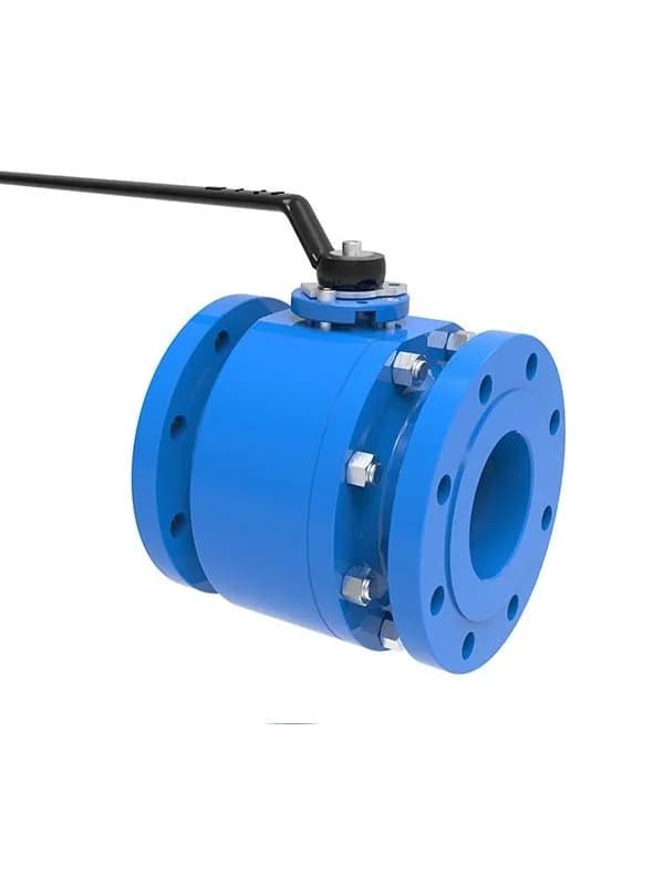
Válvula de Bola Flotante de Acero Forjado
Una válvula de bola flotante de acero forjado usa la presión de línea para empujar la bola contra el asiento aguas abajo, creando un sello autoactuante sin necesidad de mecanismos externos de resorte. Esa es la idea central detrás del diseño flotante—y es exactamente por eso que este tipo de válvula sigue siendo una de las opciones más rentables para tuberías de baja a media presión en instalaciones de petróleo y gas, petroquímica y tratamiento de agua. Las válvulas de bola flotante de acero forjado FLOWKS cubren tamaños de 2" a 8" con clasificaciones de presión de Clase 150 a Clase 600. La construcción de cuerpo forjado le brinda una estructura de material más densa y uniforme en comparación con las alternativas fundidas—menos vacíos internos, mejor contención de presión y control más estricto del espesor de pared. Si está operando un sistema donde las rutas de fuga y la integridad del material importan más que mantener el presupuesto ajustado, el acero forjado es el camino a seguir. Las configuraciones de cuerpo de dos piezas y tres piezas están ambas disponibles. La de dos piezas mantiene el diseño simple—menos uniones atornilladas, ensamblaje más rápido, menor riesgo de fugas en la junta del cuerpo con el tiempo. La de tres piezas es la mejor opción cuando necesita acceder a los componentes internos para reemplazo de asientos o limpieza sin retirar toda la válvula de la tubería. En la práctica, hemos visto que los equipos de mantenimiento prefieren la de tres piezas para líneas de proceso con ciclos regulares de inspección, mientras que la de dos piezas tiende a dominar en instalaciones permanentes donde la accesibilidad no es la prioridad. El mecanismo de bola flotante en sí es sencillo. La bola se asienta entre dos asientos pero no está anclada a un trunnion fijo. Bajo presión de operación, el medio empuja la bola aguas abajo hasta que se comprime contra el asiento aguas abajo—esa compresión crea su sello. Lo que esto significa en términos reales: el rendimiento de sellado mejora a medida que aumenta la presión de línea. A presiones muy bajas (cercanas a la atmosférica), el diseño flotante depende de la elasticidad del material del asiento para el sello inicial—por eso no le ofrecemos solo una opción de asiento. Las válvulas de bola flotante de acero forjado FLOWKS vienen de serie con opciones de material de asiento PTFE, Nylon, Delrin (POM), PCTFE y PEEK reforzado, cada una cubriendo una ventana diferente de temperatura y compatibilidad química. El PTFE maneja la mayoría de las aplicaciones de uso general hasta temperaturas moderadas; el PEEK interviene cuando necesita mayor estabilidad térmica y resistencia mecánica; el Nylon y el Delrin funcionan bien para instalaciones de menor costo donde el medio no es agresivo; el PCTFE cubre servicio criogénico y de baja temperatura. Una vez que la presión de línea alcanza el rango normal de operación, la válvula refuerza automáticamente el sellado—la presión del medio mismo empuja la bola más firmemente contra el asiento, y el sello se vuelve más fuerte en lugar de más débil. Las opciones de material del cuerpo van desde acero al carbono A216 WCB para servicio general no corrosivo hasta acero inoxidable A351 CF8M y A182 F316 para entornos corrosivos y con cloruros. El WCB maneja la mayoría de las líneas de hidrocarburos y agua a temperatura ambiente sin problema. El CF8M y el F316 intervienen cuando se trata de gas agrio, salmuera o corrientes químicas que corroerían el acero al carbono en meses. La elección del material no es abstracta—determina directamente si su válvula dura cinco años o se reemplaza después de dos temporadas. Cada válvula de bola flotante de acero forjado FLOWKS está diseñada y probada según API 6D, API 608 y ASME B16.34. La capacidad a prueba de fuego según API 607 está disponible en configuraciones seleccionadas. Estos no son solo afirmaciones de etiqueta—el cumplimiento de API 6D significa que la válvula ha pasado pruebas de presión total, incluyendo sellado de asiento con gas a alta presión y verificación de integridad del cuerpo. API 608 cubre los requisitos dimensionales y de diseño específicos para válvulas de bola. ASME B16.34 rige las clasificaciones de presión-temperatura que definen lo que la válvula puede manejar realmente en servicio. Una cosa que vale la pena señalar: las válvulas de bola flotante no son la respuesta para todas las situaciones. Si su aplicación supera la Clase 600, o si necesita válvulas de mayor diámetro que manejen gas de alta presión, una válvula de bola con muñón distribuye la carga del asiento de manera más uniforme y reduce el par de operación en tamaños más grandes. El diseño de acero forjado flotante sobresale en su rango: Clase 150 a 600, diámetros de 2" a 8", medios limpios a moderadamente abrasivos. Dentro de ese margen, es difícil superar la combinación de fiabilidad de sellado, mantenimiento simple y eficiencia de costos. Válvula de Bola Multipuerto
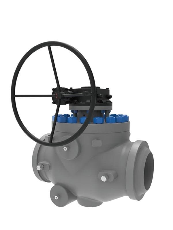
Válvula de Bola de Entrada Superior
No la saca de la tubería. Ese es el punto. Una válvula de bola de entrada superior le permite retirar la tapa del bonete desde arriba, extraer el conjunto de bola y asientos, reemplazar los sellos desgastados, reensamblar y cerrarla de nuevo——todo sin romper las conexiones de brida ni cortar la válvula de la línea. En una tubería enterrada donde la excavación cuesta más que la propia válvula, o en una instalación soldada donde el cuerpo de la válvula está unido permanentemente a la tubería, esa capacidad de acceso superior no es una característica de conveniencia. Es la razón por la que existe esta válvula. Las válvulas de bola de entrada superior FLOWKS cubren tamaños de 2" a 48" con clasificaciones de presión de Clase 150 a Clase 2500. El rango de presión se sitúa entre lo que manejan las válvulas de bola flotante (Clase 150-600) y lo que cubren las válvulas de trunnion de entrada lateral de especificación completa (hasta Clase 2500)——y ese posicionamiento es deliberado. La mayoría de las aplicaciones de tuberías enterradas y líneas soldadas en transmisión de petróleo y gas y distribución petroquímica operan dentro de la banda de Clase 150-2500, y el diseño de entrada superior está optimizado exactamente para esa ventana de servicio. Obtiene la confiabilidad de la bola anclada por trunnion y el sellado bidireccional con resortes, pero en una configuración de cuerpo construida para acceso de mantenimiento en línea en lugar de la conveniencia de entrada lateral. El principio de anclaje por trunnion funciona aquí de la misma manera que en los diseños de entrada lateral. La bola está fijada en los muñones superior e inferior del eje, y los asientos con resorte presionan independientemente contra la superficie de la bola para crear sellos desde las direcciones aguas arriba y aguas abajo. El sellado bidireccional significa que la válvula mantiene la presión independientemente de la dirección del flujo——crítico en tuberías de transmisión donde las sobrepresiones pueden invertir el flujo momentáneamente, y donde los procedimientos de aislamiento de doble bloqueo y purga requieren que ambos asientos sellen de manera confiable antes de que una sección aguas abajo se abra para trabajos. El diseño del bonete de entrada superior tiene una implicación estructural que vale la pena entender. Debido a que todo el conjunto interno——bola, asientos, vástago——se carga a través de la abertura superior, la tapa del bonete y su empernado soportan la carga completa de presión interna además de mantener el sello del cuerpo. Esto significa que la brida del bonete, la junta y el patrón de pernos están diseñados con un estándar más estricto que el que encontraría en una válvula de entrada lateral donde la tapa lateral solo maneja una porción del diferencial de presión. Las válvulas de entrada superior FLOWKS utilizan un diseño de bonete robusto con un tamaño adecuado del círculo de pernos y compresión controlada de la junta para garantizar que el sello superior se mantenga a través de ciclos de presión, variaciones térmicas y servicio a largo plazo sin desarrollar vías de filtración. El bonete no es solo una tapa; es un límite de presión. Donde esta válvula realmente demuestra su valor: líneas de transmisión de gas enterradas, tuberías subterráneas de petróleo crudo, puntos de conexión submarinos y cualquier instalación soldada donde retirar la válvula de la línea significa cerrar una sección, excavar si está bajo tierra, o hacer un derivación en caliente——todo lo cual cuesta órdenes de magnitud más que el reemplazo del asiento en sí. En esas instalaciones, la economía del mantenimiento es simple. Reemplace los asientos desde la parte superior en horas, o cierre y desentierre la línea durante días. El diseño de entrada superior hace posible la primera opción. Los materiales del cuerpo cubren los grados esenciales: acero al carbono A216 WCB para servicio estándar de transmisión y tuberías de servicios públicos, acero inoxidable A351 CF8M para medios corrosivos y ambientes de gas agrio, y dúplex A182 F51 para condiciones que requieren mayor resistencia mecánica junto con resistencia a la corrosión——típicamente instalaciones de tuberías costa afuera y costeras donde la exposición a la sal y la corrosión bajo tensión son consideraciones de diseño realistas. La selección del material sigue la misma lógica que en nuestras otras series de válvulas de bola: adaptar la aleación del cuerpo a lo que el fluido de proceso y el entorno externo le lanzarán durante la vida útil prevista de la válvula. Cada válvula de bola de entrada superior FLOWKS cumple con los requisitos de API 6D y API 607. API 6D rige el diseño completo, la producción y el régimen de pruebas de presión: integridad de la carcasa, verificación del sellado del asiento a alta y baja presión, y pruebas de resistencia al ciclado operativo. API 607 certifica el rendimiento a...
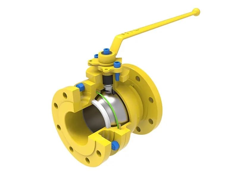
Válvula de Bola Flotante de Fundición
Misma estructura de bola flotante, mismo rango de tamaños: de 2" a 8", Clase 150 a 600, pero el cuerpo cuenta una historia diferente. Una válvula de bola flotante de acero fundido se forma vertiendo metal fundido en un molde de precisión, lo que ofrece algo que las válvulas forjadas no pueden replicar fácilmente: pasajes de flujo internos que siguen contornos más suaves y graduales. Eso podría sonar como un detalle menor, pero en líneas de proceso que transportan medios viscosos o lodos con sólidos suspendidos, la diferencia entre una esquina interna afilada y una redondeada se manifiesta en menor resistencia al flujo y menos acumulación de sedimentos con el tiempo. La construcción de cuerpo fundido no es un compromiso: es una elección de ingeniería deliberada para ciertas condiciones operativas. Las válvulas de bola flotante de acero fundido FLOWKS vienen en configuraciones de cuerpo de dos piezas y tres piezas, igual que la serie forjada. La de dos piezas mantiene todo compacto: menos uniones atornilladas, ensamblaje más simple, menor probabilidad de fugas en la junta del cuerpo después de años de ciclos térmicos. La de tres piezas es lo que necesitas si la línea recibe atención de mantenimiento periódica y prefieres cambiar los asientos sin desatornillar la válvula de la tubería. La elección entre ambas no se trata de fundición versus forjado; se trata de cómo trabaja realmente tu equipo de mantenimiento en la tubería. El principio de sellado de bola flotante funciona de manera idéntica aquí: la presión de línea empuja la bola aguas abajo contra el asiento, y el sello se auto-refuerza a medida que aumenta la presión operativa. A presiones bajas o casi atmosféricas, el sellado inicial depende de la elasticidad del material del asiento, razón por la cual FLOWKS equipa estas válvulas con cinco opciones estándar de asiento: PTFE para rangos de temperatura de uso general, PEEK reforzado donde importan la estabilidad térmica y la resistencia mecánica, Nylon y Delrin (POM) para instalaciones sensibles al costo con medios no agresivos, y PCTFE para servicio de baja temperatura y criogénico. Una vez que la línea alcanza la presión operativa normal, la válvula aprieta automáticamente su sello: la presión del medio empuja la bola con más fuerza contra el asiento aguas abajo, y el sellado se fortalece, no se debilita. Ahora la pregunta real que la mayoría de los ingenieros hacen: ¿fundido o forjado, cuál necesito realmente? Aquí está el desglose práctico. Las válvulas de cuerpo fundido tienen una clara ventaja de costo, particularmente cuando se especifican múltiples unidades en un proyecto: el proceso de moldeo escala eficientemente, y el precio unitario lo refleja. Para tuberías que manejan fluidos de proceso estándar a temperaturas y presiones moderadas, dentro del rango Clase 150-600, la construcción fundida es más que adecuada. La diferencia de densidad del material que ostentan las válvulas forjadas importa más cuando se empuja hacia el extremo superior del rango de presión o se operan sistemas donde incluso un vacío interno microscópico podría convertirse en una ruta de fuga bajo estrés sostenido de alta presión. Si sus condiciones de operación se sitúan cómodamente en el medio del rango de especificación—y la mayoría de las aplicaciones de baja a media presión lo hacen—el acero fundido ofrece el mismo rendimiento funcional a un precio más bajo. Las opciones de material del cuerpo siguen los mismos grados ASTM: acero al carbono A216 WCB para servicio rutinario de hidrocarburos y agua, acero inoxidable A351 CF8M y A351 CF8 para entornos corrosivos que involucran cloruros, ácidos o exposición a gas agrio. El proceso de fundición maneja bien estas composiciones de aleación—las fundiciones de acero inoxidable y al carbono han sido la columna vertebral de la producción industrial de válvulas durante décadas, y las propiedades del material están bien caracterizadas en miles de unidades instaladas en todo el mundo. Cada válvula de bola flotante de acero fundido FLOWKS cumple con los requisitos de API 6D, API 608 y ASME B16.34. Las configuraciones a prueba de fuego API 607 están disponibles en modelos seleccionados. La certificación API 6D significa pruebas de sellado del asiento a presión total e integridad del cuerpo, no solo un ejercicio de papeleo. API 608 establece la base dimensional y de diseño para la construcción de válvulas de bola. ASME B16.34 define el envolvente de presión-temperatura dentro del cual la válvula está clasificada para operar—y permanecer dentro de ese envolvente es lo que mantiene la línea segura y la válvula sellada.
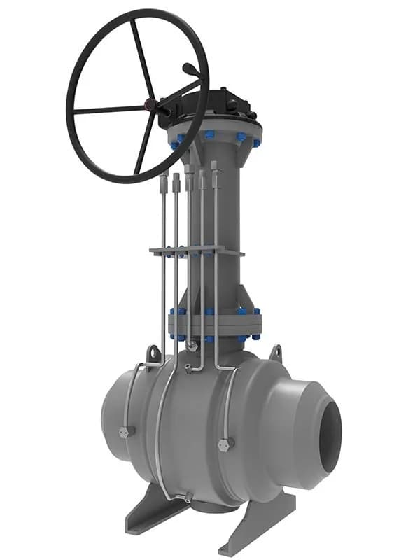
Válvula de Bola para Tubería Enterrada (Totalmente Soldada)
Sin uniones atornilladas. Sin juntas de cuerpo. Sin conexiones bridadas donde el cuerpo de la válvula se divide en piezas. Una válvula de bola para tubería enterrada totalmente soldada es una carcasa única y continua: todo el cuerpo se fusiona mediante soldadura en un solo límite de presión con cero uniones mecánicas que interrumpan el envolvente de contención. Esa simplicidad estructural es toda la razón de existir de esta válvula. En una línea de transmisión de gas enterrada o una tubería subterránea de petróleo crudo, la válvula se instala, recubre, inspecciona y luego se entierra bajo tres pies de suelo, y permanece allí durante veinte a treinta años. Nadie va a excavarla para apretar un perno del cuerpo o reemplazar una junta de bonete. La válvula debe mantener sin intervención de mantenimiento, y un cuerpo totalmente soldado elimina cada unión externa que podría desarrollar una ruta de fuga con el tiempo por ciclos térmicos, exposición a humedad del suelo y presión interna sostenida. Las válvulas de bola para tubería enterrada FLOWKS están diseñadas y construidas exactamente para esa realidad de servicio. La estructura de bola anclada por muñón con asientos con resorte proporciona sellado bidireccional: la válvula mantiene desde las direcciones aguas arriba y aguas abajo de forma independiente, lo cual es un requisito obligatorio para el aislamiento de tuberías donde la dirección del flujo puede invertirse durante eventos de sobrepresión o donde los procedimientos de aislamiento de doble bloqueo y purga necesitan que ambos asientos sellen antes de abrir secciones aguas abajo para trabajo. La bola permanece fijada en los muñones superior e inferior. No flota. No se desplaza bajo presión de línea. Los asientos hacen el trabajo de sellado, y lo hacen desde ambos lados. La construcción de cuerpo totalmente soldado elimina los mecanismos de fuga a largo plazo más comunes que enfrentan las válvulas de cuerpo atornillado bajo tierra. La relajación de los pernos del cuerpo durante años de servicio, causada por ciclos térmicos, vibración por sobrepresiones en la tubería y fluencia en el material de la junta, es un modo de falla bien documentado en válvulas de bola enterradas con cuerpo atornillado. Los pernos pierden precarga lentamente, la compresión de la junta disminuye y se desarrolla una ruta de fuga lenta en la unión del cuerpo que nadie detecta hasta que el monitoreo de emisiones la capta años después. Una válvula totalmente soldada no tiene esa unión. El cuerpo es una soldadura continua. Las únicas penetraciones externas son el orificio del vástago para el montaje del actuador y, en algunas configuraciones, un puerto de mantenimiento de acceso superior. Dos penetraciones en lugar de las cuatro a seis que encontraría en un diseño de cuerpo atornillado, y esa reducción en aberturas externas se traduce directamente en menor riesgo de emisiones fugitivas y menos puntos de prueba ISO 15848 que deben mantener la integridad del sello durante toda la vida útil de la válvula. La protección contra la corrosión para servicio enterrado no es opcional: está integrada en la especificación del producto. Las válvulas de bola para tuberías enterradas FLOWKS reciben sistemas de recubrimiento externo diseñados para enterramiento directo en suelo: FBE (epoxi fusionado por fusión) como barrera anticorrosiva base, con recubrimiento 3PE (polietileno de tres capas) disponible para instalaciones donde la química del suelo, el contenido de humedad o el riesgo de corrosión microbiológicamente influenciada (MIC) exijan capas de protección adicionales. El sistema de recubrimiento cubre toda la superficie externa del cuerpo, incluidas las soldaduras y zonas de transición donde una discontinuidad del recubrimiento crearía puntos localizados de iniciación de corrosión. Las superficies internas siguen la práctica estándar de recubrimiento de tuberías: limpias, inspeccionadas y protegidas contra la corrosión de almacenamiento y tránsito antes de la instalación. Los diseños de válvula también incorporan características de continuidad eléctrica para la integración del sistema de protección catódica: el cuerpo de la válvula proporciona una vía metálica continua para el flujo de corriente de protección catódica a través de la sección instalada, garantizando que la válvula enterrada reciba el mismo nivel de protección contra la corrosión que la propia tubería. El acceso de mantenimiento se realiza por la parte superior. El vástago y el montaje del actuador se extienden verticalmente por encima del cuerpo de la válvula, accesibles mediante una extensión sobre el suelo o un pozo de válvulas. La sustitución de asientos y sellos se puede realizar sin retirar la válvula de la tubería: el procedimiento de mantenimiento interno accede al anillo de asiento a través del orificio de la válvula utilizando herramientas especializadas, o mediante un...
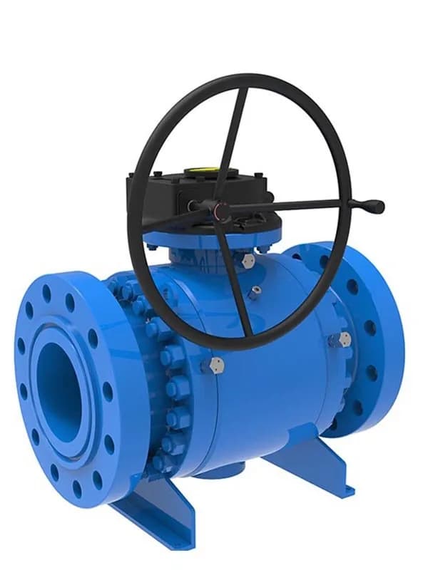
Válvula de Bola Montada en Muñón de Acero Forjado
La bola no flota. Está anclada——fijada en los muñones superior e inferior al cuerpo de la válvula, lo que significa que permanece centrada en el paso de flujo independientemente de la presión de línea. Los asientos son los que se mueven. Con resorte, aguas arriba y aguas abajo, cada asiento presiona de forma independiente contra la superficie de la bola para crear un sello bidireccional. Esa es la diferencia fundamental entre una válvula de bola montada en muñón y el diseño flotante, y importa más de lo que la mayoría de las hojas de especificaciones dejan entrever. Las válvulas de bola de acero forjado montadas en muñón de FLOWKS manejan rangos de presión desde Clase 150 hasta Clase 2500——un rango que cubre desde distribución de agua a baja presión hasta transmisión de gas a alta presión y servicio de crudo amargo. La construcción de cuerpo forjado es particularmente relevante en el extremo superior de este espectro. El acero forjado ofrece una estructura interna más homogénea con menos defectos relacionados con la fundición; bajo carga sostenida de alta presión, esa ventaja de densidad se traduce en mejor contención de presión y menor riesgo de que la porosidad de la pared del cuerpo se convierta en una vía de fuga a largo plazo. Si está especificando válvulas para Clase 600 y superior, la construcción de cuerpo forjado no es opcional——es práctica estándar en cualquier especificación de tuberías seria. El diseño de cuerpo con entrada lateral es la configuración predeterminada para esta serie. Los conjuntos de bola y asientos se cargan a través de una abertura lateral en el cuerpo de la válvula en lugar de desde arriba, lo que simplifica el mantenimiento en campo——puede acceder a los componentes internos sin romper las conexiones de brida principales en ambos lados de la tubería. En instalaciones de línea soldada donde la válvula está unida permanentemente a la tubería, la entrada lateral es la única forma práctica de realizar el reemplazo de asientos y sellos en línea sin cortar la válvula. Esa accesibilidad de mantenimiento por sí sola ha ahorrado más horas de parada de las que la mayoría de los ingenieros se preocupan por contar. La estructura de muñón también resuelve el problema de par que limita las válvulas de bola flotantes en tamaños más grandes. Debido a que la bola permanece fija en posición, la única fuerza que necesita superar durante la rotación es la fricción entre los anillos de asiento y la superficie de la bola——no toda la presión del medio empujando la bola contra un asiento. El resultado práctico: una válvula de bola de muñón de 20 pulgadas puede operarse con un actuador de tamaño razonable, mientras que un diseño flotante con el mismo diámetro requeriría un par de actuador que eleva el costo y la complejidad más allá de lo que la aplicación realmente necesita. Esta es la razón por la que las válvulas de bola montadas en muñón dominan las hojas de especificaciones para cualquier cosa por encima de 8 pulgadas de diámetro y Clase 600 de presión nominal. Los materiales del cuerpo cubren el rango crítico de aleaciones: acero al carbono A216 WCB para líneas de proceso y servicios estándar, acero inoxidable austenítico A351 CF8M para medios corrosivos que contienen cloruros y ácidos, acero inoxidable dúplex A182 F51 para servicios que necesitan tanto resistencia a la corrosión como mayor resistencia mecánica de la que los grados austeníticos estándar pueden ofrecer, y súper dúplex A182 F53 para los entornos más agresivos——alto contenido de cloruro, alta temperatura, alto estrés. F51 y F53 no son opciones de lujo; son necesidades de ingeniería cuando el fluido de proceso picaría y agrietaría el acero inoxidable ordinario dentro de un ciclo de servicio. Cada válvula en esta serie está diseñada y probada según API 6D y API 607, con cumplimiento de emisiones fugitivas ISO 15848 disponible en configuraciones especificadas. API 6D rige el régimen completo de diseño, fabricación y prueba para válvulas de bola de tubería——pruebas de presión, verificación de sellado de asientos y resistencia operativa están todas cubiertas. API 607 certifica el rendimiento a prueba de fuego: la válvula mantiene la integridad del asiento a través de un evento de exposición al fuego y vuelve a sellar efectivamente después. ISO 15848 establece el estándar de baja fuga para el sellado del vástago de la válvula——relevante cuando su proceso maneja medios volátiles, inflamables o tóxicos donde las emisiones fugitivas deben permanecer dentro de los límites permitidos. Estos tres estándares juntos definen lo que una válvula de bola de acero forjado montada en muñón tiene que demostrar antes de enviarse. Válvula de bola de 3 vías tipo Y
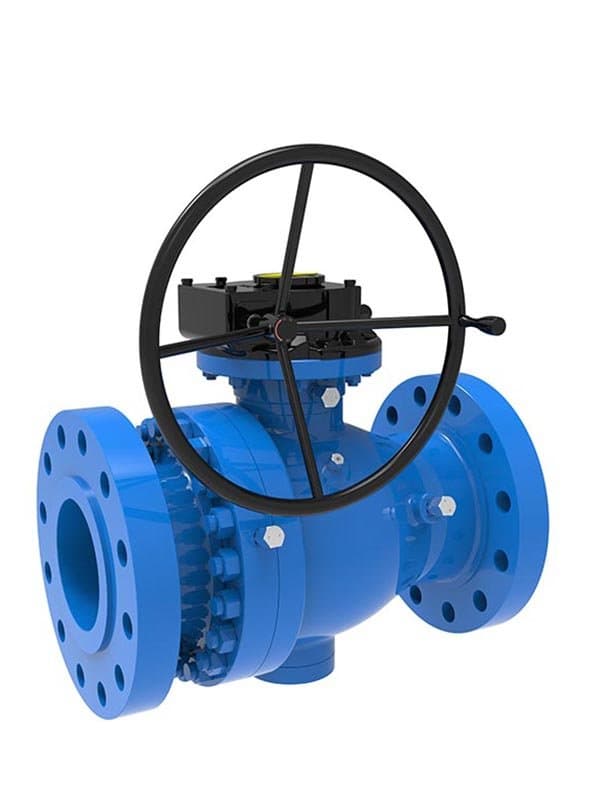
Válvula de Bola Montada en Muñón de Fundición
La misma bola anclada en muñón, los mismos asientos bidireccionales con resorte——pero el cuerpo toma forma mediante un proceso completamente diferente. Una válvula de bola de acero fundido montada en muñón se construye vertiendo metal fundido en moldes de precisión, y ese proceso de moldeo logra algo que la forja no puede igualar en tamaños grandes: permite que la cavidad interna se forme con la geometría exacta del contorno de flujo que el diseño requiere, sin las limitaciones de mecanizado que enfrentan los cuerpos forjados al tallar pasajes internos complejos. En una válvula de 36 pulgadas, esa diferencia en la calidad del camino de flujo interno no es cosmética——afecta la caída de presión, el coeficiente de flujo y cómo el medio se mueve a través del orificio de la válvula en condiciones operativas reales. Las válvulas de bola de acero fundido montadas en muñón de FLOWKS abarcan tamaños desde 2" hasta 48" con clasificaciones de presión desde Clase 150 hasta Clase 2500. La construcción de cuerpo fundido ofrece una ventaja de costo directa en tamaños de orificio grandes——por encima de aproximadamente 12 pulgadas, el proceso de forja se vuelve cada vez más costoso por unidad porque el volumen de material y la complejidad de mecanizado aumentan drásticamente, mientras que la fundición mantiene una economía unitaria relativamente estable mediante la reutilización de moldes. Para proyectos que especifican múltiples válvulas de orificio grande en una red de tuberías, esa diferencia de costo se acumula rápidamente. El acero fundido no es la opción económica; es la opción práctica cuando la especificación exige válvulas grandes en cantidades que importan para el resultado final del proyecto. El diseño de cuerpo con entrada lateral también se aplica aquí. El conjunto de bola y asientos se carga a través de una abertura lateral en el cuerpo fundido, mismo principio que la serie forjada——los componentes internos se pueden acceder sin desconectar las bridas de tubería en ambos extremos, y en instalaciones soldadas, el acceso de entrada lateral es lo que hace posible el mantenimiento en línea. El cuerpo fundido tiene una ventaja sutil en esta configuración: el área de la brida de la tapa de entrada lateral se puede diseñar con un espesor de pared y una geometría de círculo de pernos más generosos durante el proceso de fundición, porque el molde permite una complejidad de forma que requeriría pasadas de mecanizado adicionales en un cuerpo forjado. Bridas de tapa más gruesas significan una compresión de junta más confiable a lo largo de años de ciclos térmicos y fluctuaciones de presión. Ese detalle no aparece en una hoja de datos, pero se manifiesta en el campo. La estructura de muñón resuelve los mismos desafíos de par y sellado que en la versión forjada. La bola permanece anclada——sujeta en la parte superior e inferior——y los asientos con resorte crean sellos independientes aguas arriba y aguas abajo. La capacidad de sellado bidireccional significa que la válvula mantiene presión desde cualquier dirección, lo cual importa en sistemas de tuberías donde el flujo puede invertirse durante condiciones de perturbación o donde se requiere aislamiento de doble bloqueo para un acceso de mantenimiento seguro. Debido a que la bola no se desplaza bajo la presión del medio, el par de operación se mantiene predecible en todo el rango de presión. Una válvula de bola de muñón fundida de 24 pulgadas en Clase 600 requiere un actuador dimensionado solo para la fricción del asiento, no para superar la presión de línea contra una bola flotante——y esa previsibilidad de par se mantiene hasta el servicio Clase 1500 y Clase 2500, donde los diseños flotantes simplemente no pueden operar a esas clasificaciones de presión independientemente del material del cuerpo. Los materiales del cuerpo se alinean con los mismos grados de aleación críticos: acero al carbono A216 WCB para servicio general de proceso y utilidades, acero inoxidable austenítico A351 CF8M para ambientes corrosivos, dúplex A182 F51 y súper dúplex A182 F53 para condiciones de alto estrés y alto contenido de cloruro donde el acero inoxidable austenítico estándar alcanza sus límites. El proceso de fundición maneja particularmente bien el CF8M——las piezas fundidas de acero inoxidable austenítico tienen décadas de historial de servicio comprobado en aplicaciones petroquímicas y costa afuera. F51 y F53 en forma fundida entregan las mismas propiedades mecánicas dúplex; el proceso de fundición se ha refinado para mantener el equilibrio de fases y el control de microestructura requeridos que otorgan a los grados dúplex su combinación de resistencia a la corrosión y resistencia mecánica. Todas las válvulas cumplen con API 6D y API 607, con cumplimiento de emisiones fugitivas ISO 15848 en configuraciones especificadas. La certificación API 6D cubre el régimen completo de diseño,...
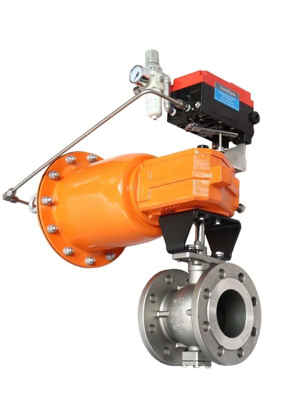
Válvula de Bola de Puerto V Neumática
Una válvula de bola estándar ofrece dos posiciones——abierta y cerrada. Eso es suficiente para servicio de aislamiento. Pero cuando el proceso realmente necesita regulación de flujo——controlando cuánto medio pasa en posiciones de apertura parcial——una válvula de bola de orificio redondo se convierte en una mala elección. La abertura circular crea una característica de flujo lineal donde pequeños movimientos rotacionales cerca de la posición cerrada producen cambios de flujo desproporcionadamente grandes, haciendo casi imposible la estrangulación precisa. La válvula de bola de puerto en V fue diseñada para resolver exactamente este problema, y lo hace con una sola modificación geométrica: la bola lleva una muesca en forma de V en lugar de un orificio circular completo. Las válvulas de bola de puerto en V de FLOWKS utilizan una bola segmentada con un perfil de muesca en V mecanizado con precisión. A medida que la bola rota de cerrada a abierta, la muesca en V revela progresivamente más área de flujo contra el asiento de la válvula——pero el aumento de área sigue una curva de característica aproximadamente de porcentaje igual en lugar de una lineal. Lo que eso significa en términos operativos: en posiciones de apertura baja (10-30%), cada rotación incremental produce un aumento de flujo pequeño y controlado. La válvula mantiene el proceso estable cerca del flujo mínimo sin oscilaciones ni caza. En posiciones de apertura más alta (60-80%), cada rotación entrega un incremento de flujo mayor——dando al sistema de control sensibilidad exactamente donde la necesita. Ese comportamiento inherente de porcentaje igual hace que las válvulas de bola de puerto en V sean significativamente más fáciles de ajustar en bucles de control de proceso en comparación con válvulas de característica lineal, y es por eso que se han convertido en la opción predeterminada de válvula de bola de estrangulación en aplicaciones químicas, petroquímicas y de pulpa y papel donde la estabilidad del flujo en posiciones bajas importa más que el rendimiento bruto a plena apertura. El borde de la muesca en V hace algo más que los diseños de orificio redondo no pueden——corta. Cuando la bola rota hacia la posición cerrada, el borde en V actúa como una cuchilla que pasa a través del asiento, cortando material fibroso, sólidos suspendidos, fibras de pulpa y residuos viscosos que de otro modo se atascarían entre la bola y el asiento en un diseño convencional. Pasta de papel, líneas de lodo, aguas residuales con desechos suspendidos, soluciones de polímeros con contaminantes fibrosos——estos son los tipos de medio que convierten las válvulas de bola estándar en dolores de cabeza de mantenimiento. El borde de puerto en V los maneja cortando el material obstructivo en cada ciclo de cierre. No es un filtro; es una interfaz de asiento autolimpiante que reduce la acumulación entre las superficies de sellado. La estructura de bola anclada con muñones se aplica aquí. La bola está fijada en los muñones superior e inferior——no flota ni se desplaza bajo la presión de línea, lo que mantiene el perfil de muesca en V precisamente alineado con el asiento en cada posición rotacional. La estabilidad de alineación del asiento es crítica para una válvula de estrangulación porque la curva de característica de flujo depende de la relación geométrica exacta entre la abertura de la muesca en V y el orificio del asiento. Si la bola se desplaza ligeramente bajo presión (como permiten los diseños flotantes), el área de flujo efectiva en cada posición cambia de manera impredecible, y su bucle de control cuidadosamente ajustado comienza a derivar. El anclaje con muñones elimina esa fuente de deriva por completo. Los asientos con resorte presionan independientemente contra la bola desde las direcciones aguas arriba y aguas abajo, creando sellado bidireccional——la válvula mantiene la estanqueidad en ambas direcciones cuando está totalmente cerrada, lo que importa tanto para el aislamiento de seguridad del proceso como para el control de flujo. Las opciones de material del asiento cubren el rango necesario para servicio de estrangulación. PTFE funciona para medios limpios de uso general a temperaturas moderadas. PEEK maneja servicio a temperatura elevada donde la resistencia mecánica del PTFE comienza a ablandarse. Las configuraciones de asiento metálico duro——típicamente recubrimiento de estelita o carburo de tungsteno en la superficie de contacto del asiento——están disponibles para medios abrasivos, servicio de vapor a alta temperatura y aplicaciones donde la válvula cicla frecuentemente entre posiciones de estrangulación y cierre. Los asientos metálicos sacrifican algo de estanqueidad de asiento blando a cambio de resistencia al desgaste que soporta el contacto repetido del borde en V. La elección entre asientos blandos y duros no es teórica——depende de si su proceso opera lo...
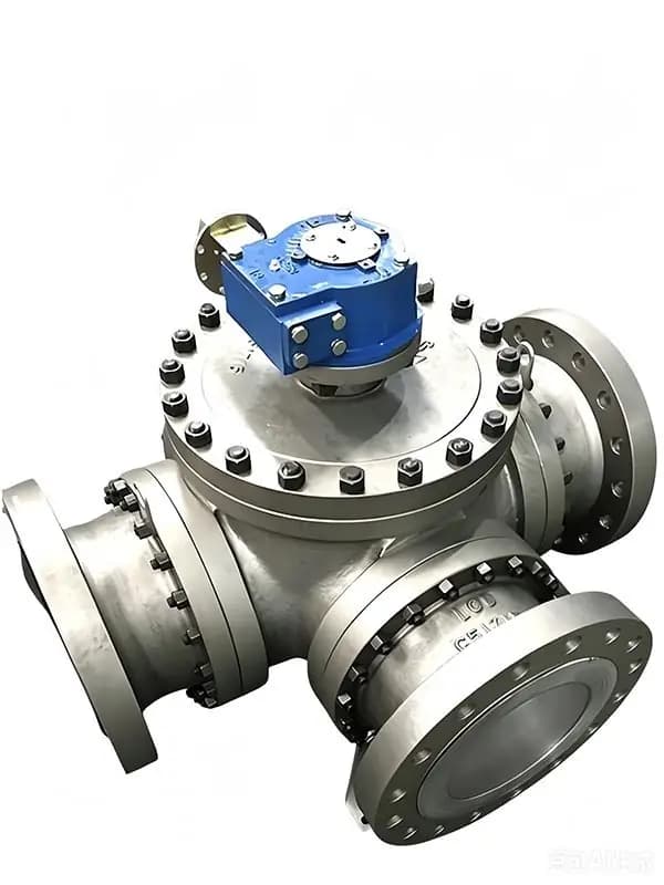
Válvula de Bola Multivías
La mayoría de los diseños de tuberías manejan la desviación de flujo de la manera convencional: instalar dos o tres válvulas de bola estándar de dos puertos en tuberías ramificadas, agregar codos y conexiones en T para dirigir el medio entre diferentes líneas de proceso, y esperar que el conjunto se mantenga sin desarrollar fugas en cada brida y conexión roscada. Funciona. Pero es costoso de construir, costoso de mantener, y crea más puntos potenciales de fuga de los que el proceso realmente necesita. Una válvula de bola multipuerto reemplaza todo ese arreglo con un solo cuerpo de válvula: una instalación, un sistema de sellado, un actuador (si lo necesita), y una ruta de flujo que cambia de dirección al girar la bola en lugar de abrir y cerrar múltiples válvulas en secuencia. Las válvulas de bola multipuerto FLOWKS cubren toda la gama de configuraciones de puertos: diseños de tres vías con puerto en L y puerto en T para conmutación básica de dirección entre dos rutas de flujo, válvulas de cuatro vías para desviación y aislamiento simultáneos a través de múltiples ramales de tubería, y configuraciones de cinco vías para requisitos de ruteo complejos que las válvulas estándar de dos puertos simplemente no pueden manejar sin conjuntos de colectores elaborados. Las configuraciones de sellado varían según el diseño: opciones de tres vías con tres sellos, tres vías con dos sellos y tres vías con cuatro sellos están disponibles dependiendo de cuántas rutas de flujo necesiten aislarse de manera independiente en cualquier posición de la bola. La configuración correcta no es algo que se elija de un catálogo. Depende de su diseño de tubería específico, cuántas direcciones debe conmutar el medio, qué rutas deben bloquearse mientras otras permanecen abiertas, y si el proceso requiere desviación simultánea o secuencial. Por eso estas válvulas se diseñan bajo pedido, no se producen en masa en configuraciones estándar esperando que una de ellas coincida con su aplicación. La configuración de puertos determina qué hace la válvula en cada posición de rotación. Una válvula de tres vías con puerto en L dirige el flujo entre dos de tres tuberías conectadas, con el tercer puerto bloqueado: paso directo o desviado, una ruta activa a la vez. Una de tres vías con puerto en T permite el flujo a través de dos puertos simultáneamente o desvía entre cualquiera de las tres conexiones: más flexibilidad de ruteo, pero menos control de aislamiento porque al menos dos puertos permanecen abiertos en cada posición. Los diseños de cuatro y cinco vías añaden mayor complejidad de ruteo: el flujo puede dirigirse, combinarse o aislarse a través de múltiples ramales en una sola rotación de la válvula, reemplazando conjuntos de colectores que de otro modo requerirían de cuatro a seis válvulas individuales y las conexiones de tubería entre ellas. Cada puerto y sello adicional en una válvula multipuerto elimina un conjunto completo de válvula más accesorio que de otro modo existiría en el sistema de tuberías, y cada eliminación quita un punto potencial de fuga, un elemento de mantenimiento y una pieza de hardware que debe adquirirse, instalarse e inspeccionarse por separado. Estas son válvulas diseñadas a medida. La disposición de puertos, la geometría del orificio de la bola, la selección del material del asiento, el material del cuerpo y el tipo de conexión final se especifican para coincidir con las condiciones exactas del proceso que servirá la válvula: tipo de medio, presión de operación, rango de temperatura, frecuencia de ciclado y la lógica de desviación específica que requiere el sistema de tuberías. Una válvula de tres vías con puerto en L que maneja agua limpia en Clase 150 recibe un paquete de especificaciones diferente que una válvula de cuatro vías que dirige gas ácido entre múltiples unidades de procesamiento en Clase 600. El equipo de ingeniería trabaja a partir del diseño de tuberías y los requisitos de desviación del cliente, no de una matriz de productos estándar. Esa capacidad de personalización es el producto: no solo la válvula en sí, sino el proceso de ingeniería que determina exactamente qué configuración, qué disposición de sellado y qué combinación de materiales funcionarán de manera confiable en la aplicación específica durante el intervalo de servicio previsto. La construcción del cuerpo sigue los mismos estándares de calidad de material que toda la serie de válvulas de bola FLOWKS. Cuerpos de acero forjado para aplicaciones de alta presión y alta integridad donde la densidad del material y la contención de presión importan. Cuerpos de acero fundido para tamaños más grandes y proyectos sensibles a la cantidad donde la economía de fundición ofrece mejor valor unitario. Los materiales del cuerpo incluyen acero al carbono A216 WCB para servicio de proceso general, acero inoxidable A351 CF8M para medios corrosivos, dúplex...
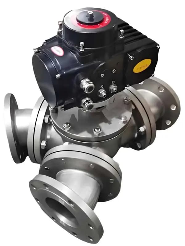
Válvula de Bola de 3 Vías Tipo Y
Las válvulas de bola de tres vías con puerto L y puerto T disponen sus tres conexiones en intersecciones de noventa grados——un orificio de paso recto y un puerto de derivación perpendicular a él. El medio entra a través de una rama y tiene que hacer un giro brusco de ángulo recto para salir a través del puerto perpendicular. Esa redirección de noventa grados crea resistencia al flujo, caída de presión y turbulencia justo en el punto donde el proceso necesita un flujo suave e ininterrumpido. En servicio de desvío——dividiendo una sola corriente de entrada en dos direcciones de salida, o fusionando dos flujos de entrada en una sola salida——ese codo de ángulo recto es una penalización de rendimiento que se acumula durante toda la vida útil de la válvula. Cada psi de presión perdida en el giro significa menos presión disponible aguas abajo, mayor entrada de energía de bombeo requerida y más desgaste en las superficies de los asientos donde la intensidad de turbulencia alcanza su punto máximo. La configuración en Y dispone los tres puertos con una separación angular más amplia—típicamente acercándose a 120 grados de forma simétrica, o en ángulos personalizados para diseños de desvío específicos. En lugar de forzar el medio a través de una esquina de noventa grados, la geometría en Y proporciona ángulos de transición más graduales entre las rutas de flujo. El resultado es un paso interno más suave con menor cambio de velocidad en el punto de desvío, menos generación de turbulencia y un coeficiente de flujo (Cv) mediblemente más alto en comparación con un diseño de puerto en L o en T de tamaño equivalente en la misma posición de desvío. Esa diferencia en el rendimiento de flujo importa más en aplicaciones donde la válvula opera en modo de desvío de forma continua—no solo cambiando entre rutas ocasionalmente, sino dividiendo o combinando flujos activamente como condición operativa normal. Sistemas de distribución de agua de refrigeración, rutas de derivación de intercambiadores de calor, desvío de corrientes en procesos químicos y cualquier aplicación donde la válvula pasa la mayor parte de su vida útil en una configuración de flujo parcial en lugar de ciclar entre apertura total y cierre total—estos son los escenarios donde la geometría en Y ofrece una ventaja hidráulica tangible sobre los giros internos más pronunciados que imponen las configuraciones en L y en T. Las válvulas de bola de tres vías en Y de FLOWKS utilizan una bola mecanizada con precisión cuya geometría del orificio está adaptada al diseño del cuerpo de puertos en Y. El orificio de la bola no es solo un agujero pasante recto—está conformado para alinearse con la relación angular entre los tres puertos del cuerpo en cada posición rotacional, asegurando que la ruta de flujo a través de la válvula siga las transiciones del ángulo en Y del cuerpo sin introducir interrupciones geométricas internas adicionales. En la posición de desvío, el orificio conecta el puerto de entrada con ambas ramas de salida a través de canales que siguen la separación angular natural que proporciona el cuerpo en Y. En la posición de paso directo (si la lógica de desvío lo requiere), el orificio alinea dos puertos directamente y bloquea el tercero. Cada posición en la que opera la válvula ha sido diseñada para la geometría de ruta de flujo que esa posición requiere—no adaptada de un patrón de orificio estándar de dos puertos y esperando que funcione en un cuerpo de tres puertos. La bola está anclada con muñones—fijada en los ejes superior e inferior dentro del cuerpo, mantenida en posición independientemente de la presión de línea. Los asientos cargados por resorte presionan independientemente contra la bola desde cada dirección de puerto, creando sellos individuales para cada ruta de flujo. Debido a que una válvula en Y tiene tres puertos en lugar de dos, el sistema de sellado proporciona tres puntos de contacto de asiento independientes en lugar de dos—aguas arriba, aguas abajo-izquierda y aguas abajo-derecha (o al revés, dependiendo de la dirección del flujo). Cada asiento sella por sí mismo. Si un puerto está bloqueado mientras los otros dos permanecen abiertos, el asiento del puerto bloqueado mantiene la presión de forma independiente sin depender de la condición de sellado de los puertos activos. Esa capacidad de aislamiento por puerto es crítica en aplicaciones de desvío donde una rama necesita cerrarse mientras el flujo continúa a través de la otra—la rama bloqueada debe mantener la estanqueidad independientemente de lo que ocurra en las rutas de flujo activas. Las opciones de material de asiento incluyen PTFE para medios limpios de uso general en rangos de temperatura moderados, PEEK reforzado para condiciones de mayor temperatura y estrés mecánico, Nylon y Delrin (POM) para servicio rentable con fluidos no agresivos, PCTFE para servicio a baja temperatura y...
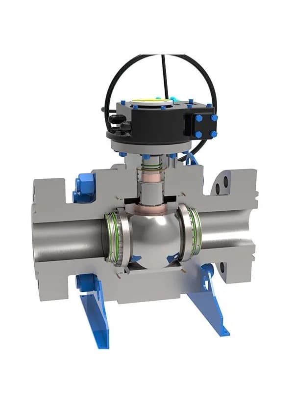
Válvula de Bola Montada en Muñón — Placa de Soporte
La mayoría de las válvulas de bola montadas con muñón anclan la bola a través de extensiones de eje externas: el vástago superior sobresale a través del cuerpo para el montaje de manija o actuador, y el pasador de muñón inferior pasa a través de la carcasa del cuerpo hacia una placa de soporte inferior en el exterior. Dos penetraciones externas, dos ubicaciones de sellado del vástago, dos puntos potenciales de emisiones fugitivas. Ese es el diseño estándar, y funciona. Pero conlleva una compensación estructural que se muestra más claramente en dos lugares: las pruebas de cumplimiento de bajas emisiones ISO 15848 y la integridad del sellado del asiento a largo plazo bajo ciclos de alta presión sostenidos. La válvula de bola de muñón tipo placa de soporte FLOWKS elimina por completo la penetración externa inferior. En lugar de un pasador de muñón inferior que atraviesa el cuerpo de la válvula, una placa de soporte inferior se integra en la cavidad del cuerpo mismo: la placa se asienta dentro del cuerpo, soportando directamente el cojinete del muñón inferior de la bola. Ningún eje penetra la carcasa del cuerpo en la parte inferior. Sin sello externo, sin prensaestopas, sin posible vía de fuga en esa ubicación. La placa de soporte superior funciona de la misma manera: soporta la carga del cojinete superior de la bola dentro del cuerpo en lugar de depender de un inserto de manguito externo presionado en la bola desde afuera. Dos placas de soporte internas manejan la carga completa de empuje del medio, y de ahí proviene la afirmación de "soporte más fuerte". Las placas distribuyen la fuerza de empuje en un área de contacto más amplia de lo que podría un solo muñón de eje, lo que significa menos tensión localizada en las superficies de cojinete y más rigidez estructural bajo carga de presión diferencial en Clase 1500 y Clase 2500. El rango de tamaños es de 2" a 48", con clasificaciones de presión de Clase 150 a Clase 2500: la misma cobertura que nuestra serie estándar de válvulas de bola de muñón de acero forjado. La construcción de cuerpo forjado también se aplica aquí. El cuerpo forjado le brinda la ventaja de densidad de material para la contención de alta presión, y el diseño de placa de soporte interna lo complementa manteniendo el límite de presión más limpio. Menos penetraciones externas en un cuerpo forjado significa menos ubicaciones donde el envolvente de presión continuo se interrumpe por un orificio de eje y un arreglo de empaquetadura. Piénselo de esta manera: una carcasa de cuerpo forjado es un recipiente a presión cerrado. Cada orificio de eje que lo atraviesa abre un agujero en ese recipiente que debe volver a sellarse con empaquetadura. El diseño de placa de soporte cierra uno de esos agujeros permanentemente. Eso no es una mejora incremental: es una actualización estructural fundamental. El principio de sellado sigue siendo basado en muñón. Los asientos con resorte presionan independientemente contra la superficie de la bola anclada desde las direcciones aguas arriba y aguas abajo, creando un sellado bidireccional. La bola no flota, no se desplaza bajo la presión de línea: permanece centrada y los asientos hacen el trabajo de sellado. Las opciones de material de asiento incluyen PTFE para servicio general, PEEK reforzado para requisitos de temperatura elevada y resistencia mecánica, Nylon y Delrin (POM) para aplicaciones rentables de medios no agresivos, y PCTFE para servicio de baja temperatura. Una vez que la presión de línea alcanza el rango operativo normal, la válvula refuerza automáticamente el sellado: la precarga del resorte combinada con la presión del medio impulsa cada asiento más firmemente contra la bola. La ventaja de emisiones fugitivas merece un análisis más detallado. Las pruebas de cumplimiento ISO 15848 miden las tasas de fuga del sello del vástago, y cada penetración de eje externo es un punto de prueba. Una válvula de bola de muñón convencional con vástagos externos superior e inferior tiene dos ubicaciones de sello independientes que ambas deben pasar. El diseño de placa de soporte elimina la penetración inferior, lo que significa un punto de prueba menos, un sello menos que puede degradarse con el tiempo y una posible vía de fuga menos que su sistema de monitoreo de emisiones debe rastrear. En la práctica, esa simplificación estructural se traduce en resultados de prueba ISO 15848 más consistentes a lo largo de la vida útil de la válvula. Los equipos de mantenimiento también se benefician: un prensaestopas menos que inspeccionar, ajustar y eventualmente reempaquetar durante el trabajo programado de parada. Materiales del cuerpo: acero al carbono A216 WCB para líneas de proceso estándar, acero inoxidable austenítico A351 CF8M para medios corrosivos y que contienen cloruro, acero inoxidable dúplex A182 F51 donde se requieren tanto resistencia a la corrosión como mayor...
Descripción técnica
Las válvulas de bola cortan el flujo con un cuarto de vuelta. Esa simplicidad es la razón por la que superan en número a cualquier otro tipo de válvula en una planta de proceso típica: accionamiento rápido, sellado bidireccional y un orificio totalmente abierto que permite que el medio pase con una resistencia casi nula cuando la válvula está abierta. FLOWKS fabrica configuraciones de bola flotante y montadas en muñón en tamaños de 2" a 48", con opciones de cuerpo fundido y forjado, acceso superior para mantenimiento en líneas soldadas, trim de puerto en V para servicio de modulación y diseños multipuerto para conmutación de flujo. El diseño de bola flotante depende de la presión de línea para empujar la bola contra el asiento aguas abajo: auto-reforzante a presiones más altas, económico en tamaños más pequeños. Los diseños montados en muñón anclan la bola mecánicamente y permiten que los asientos se muevan hacia ella, lo cual es necesario por encima de 8" donde la geometría flotante no puede mantener una carga uniforme del asiento, y esencial para servicio de alta presión Clase 900–2500 donde la fuerza operativa abrumaría una bola flotante. La selección del material del asiento (PTFE, Nylon, Delrin, PCTFE, PEEK reforzado) determina los límites de temperatura y la compatibilidad química. Las configuraciones con asiento metálico manejan condiciones abrasivas, de alta temperatura y criogénicas donde fallan los asientos blandos. Ya sea que necesite una válvula compacta de bola flotante de 2" para una línea de servicios o una unidad de muñón de 48" para una tubería enterrada, la simplicidad de cuarto de vuelta de la válvula de bola se escala en todos los tamaños y clases de presión en servicio industrial.
Las válvulas de bola FLOWKS cubren toda la gama industrial: desde diseños flotantes de 2" para aislamiento de servicios y procesos hasta unidades montadas en muñón de 48" para servicio de tuberías de alta presión. Las válvulas de bola flotantes (2"–8", Clase 150–600) usan presión de línea para asentar la bola contra el asiento aguas abajo, proporcionando un cierre auto-reforzante a presión de operación. Las válvulas de bola montadas en muñón (2"–48", Clase 150–2500) anclan la bola con vástagos superior e inferior, permitiendo que asientos con resorte o flotantes sellen contra la bola: presión de contacto uniforme en cada tamaño y clase de presión. Los cuerpos de acero fundido ofrecen eficiencia de costos y contornos de flujo interno más suaves para servicio de fluidos viscosos y lodos. Los cuerpos de acero forjado brindan mayor integridad estructural para contención de presión exigente. Los diseños de entrada superior permiten mantenimiento en línea en tuberías enterradas y soldadas sin retirar la válvula de la línea. Las válvulas de bola de puerto en V combinan el cierre con control de modulación mediante aberturas de bola en V caracterizadas. Las configuraciones multipuerto redirigen el flujo entre múltiples líneas de proceso con un solo cuerpo de válvula. Los materiales de asiento blando (PTFE, Nylon, Delrin, PCTFE, PEEK) cubren servicio químico general hasta alto rendimiento. Los asientos metálicos manejan condiciones abrasivas, de alta temperatura y criogénicas. Las válvulas de bola FLOWKS cumplen con API 6D, API 608 y ASME B16.34, con certificación de baja emisión ISO 15848 disponible en modelos de muñón y entrada superior.
Descargas de productos
Industrias que utilizan este producto
Aplicaciones en diversos sectores industriales.
Oil & Gas
Upstream, midstream and downstream valve solutions meeting API 6D, API 607 fire-safe requirements. From wellhead to refinery, FLOWKS provides reliable valve solutions for the most demanding oil and gas applications.
Power Generation
High-temperature and high-pressure valves for fossil fuel, nuclear, and renewable energy plants. FLOWKS gate valves and globe valves are proven in power generation service worldwide.
Water Treatment
Reliable flow control solutions for desalination, wastewater, and potable water systems. FLOWKS butterfly valves and check valves are widely used in water infrastructure projects.
LNG
Cryogenic valves engineered for liquefied natural gas processing and transportation. FLOWKS cryogenic service valves are tested to -196degC per BS 6364.
products.lookingMore
products.lookingMoreDesc
DBB Valves
FLOWKS Double Block & Bleed (DBB) valves provide dual isolation with bleed verification in a single compact body. Replacing traditional multi-valve installations, FLOWKS DBB valves reduce weight, space and potential leak paths. Available in bolted bonnet, all-welded and expanding gate designs per API 6D and API 607.
Gate Valves
FLOWKS gate valves for isolation service in piping systems. Flexible wedge, solid wedge, slab and expanding gate designs per API 600, API 602 and ASME B16.34.
Globe Valves
FLOWKS globe valves for throttling and isolation. Standard, angle, Y-pattern and bellows seal configurations per API 602 and BS 1868.
Check Valves
FLOWKS check valves prevent reverse flow. Dual plate, swing, tilting disc and lift check designs per API 594 and BS 1868.